
Drivetrain for a motor vehicle

a technology for driving a motor vehicle and a drivetrain, which is applied in the direction of interengaging clutches, rotary clutches, fluid couplings, etc., can solve the problems of electric motor heating up, low degree of efficiency of actuator arrangement, and high expenditure on valves and other hydraulic components, so as to achieve low energy requirements, good degree of efficiency, and long active duration

Inactive Publication Date: 2007-08-02
GETRAG DRIVELINE SYST
View PDF10 Cites 22 Cited by
  • Summary
  • Abstract
  • Description
  • Claims
  • Application Information

AI Technical Summary

Benefits of technology

[0010] It is an object of the present invention to specify a drivetrain of the type stated in the introduction in which a good degree of efficiency is obtained in the highest possible number of operating states, and a long active duration is possible with low energy requirements.

Problems solved by technology

Such additions often entail a high expenditure on valves and other hydraulic components in order to be able to meet the requirements stated in the introduction.
In the above-described solution based on an electric motor in connection with a mechanism and a ball ramp, this leads to the electric motor heating up, since a very high current consumption (in the region of 30 A and above) is required to keep the clutch in the closed state.
As a result of the heating effect, the actuator arrangement has a low degree of efficiency.
The same problem occurs if a friction clutch is actuated directly by means of a pump.

Method used


Image

  • Drivetrain for a motor vehicle
  • Drivetrain for a motor vehicle
  • Drivetrain for a motor vehicle

Examples


Embodiment Construction

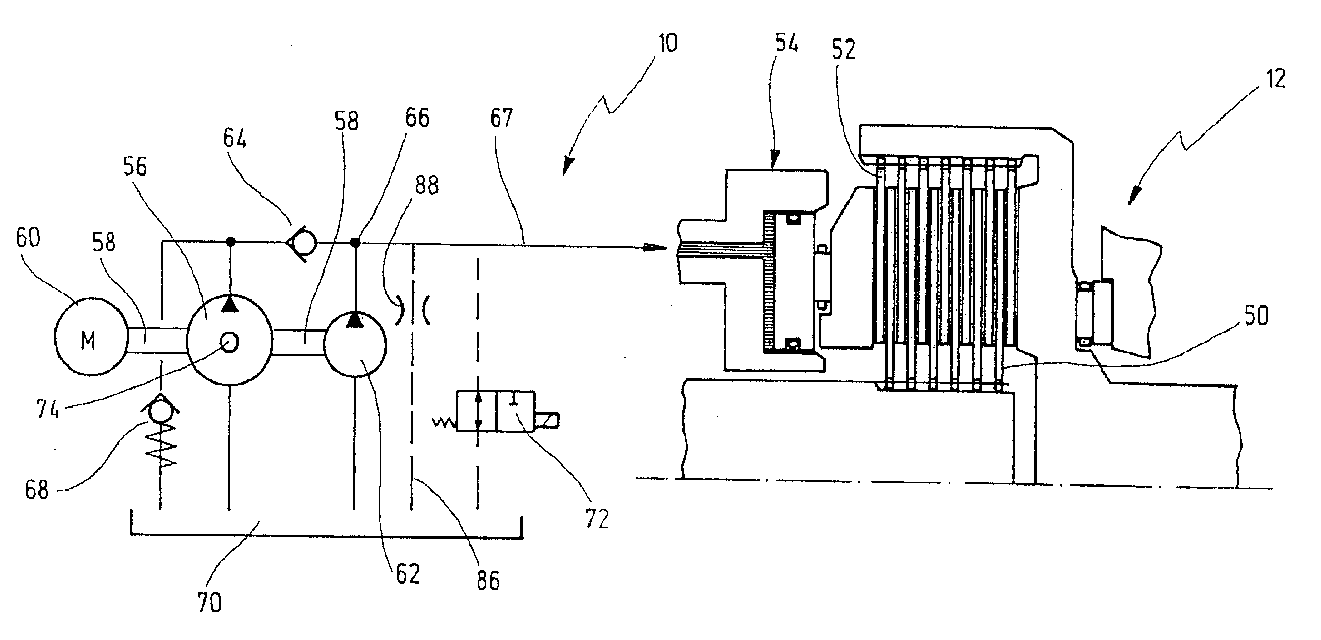
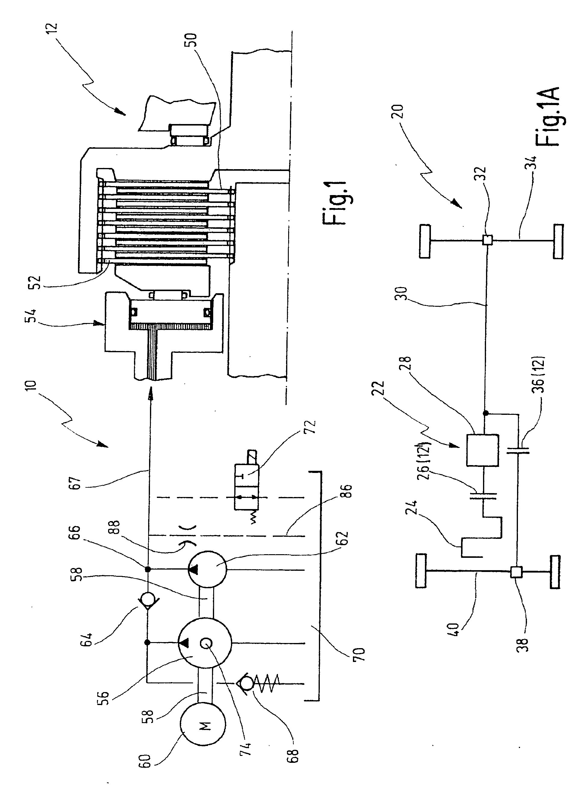
[0069] In FIG. 1, an actuator arrangement for actuating a friction clutch 12 is denoted generally by 10. The actuator arrangement 10 and the friction clutch 12 can be part of a drivetrain 22 of a motor vehicle 20 which is illustrated schematically in FIG. 1A.

[0070] The drivetrain 22 of the motor vehicle 20 has a drive motor, such as an internal combustion engine 24, and a starting and separating clutch 26. The output member of the starting and separating clutch 26 is connected to a multi-step transmission 28 for providing a plurality of gears (or to a continuously variable transmission). The output of the transmission 28 is connected via a cardan shaft 30 to a rear axle differential 32 whose output members are connected to the wheels of a rear axle 34.

[0071] The output of the transmission 28 is also connected via a friction clutch 36 to a front axle differential 38. The output members of the front axle differential 38 are connected to wheels of a front axle 40.

[0072] The illustra...


PUM


Abstract

A drivetrain for a motor vehicle has a friction clutch for transmitting drive torque for the motor vehicle and has an actuator arrangement for actuating the friction clutch. The actuator arrangement has a first actuator which is designed to close the friction clutch quickly with little force expenditure in order to thus quickly close up the play which is present in the open state of the friction clutch. The actuator arrangement has a second actuator which is designed such that, with a small stroke, it applies a large force for actuating the friction clutch in order to keep the friction clutch closed with little energy expenditure.

Description

CROSS-REFERENCE TO RELATED APPLICATIONS [0001] This application is a continuation application of international patent application PCT / EP 2005 / 007359 filed Jul. 7, 2005 and claims priority under 35 U.S.C. §119 from German patent application DE 10 2004 033 439 filed Jul. 8, 2004.BACKGROUND OF THE INVENTION [0002] The present invention relates to a drivetrain for a motor vehicle, having a friction clutch for transmitting drive torque for the motor vehicle and having an actuator arrangement for actuating the friction clutch. [0003] The use of friction clutches in drivetrains has long been known. For many years, dry friction clutches have been used in conventional manual shift transmissions as starting and separating clutches, to name just one example. [0004] For a number of years, there has also been a trend towards automatic drivetrains in which friction clutches are opened and closed automatically. This relates on the one hand to the starting and separating clutches of automatic shift...

Claims


Application Information

Patent Timeline
IPC IPC(8): F16D21/04F16D27/00
CPCF16D48/04F16D25/0638F16D48/066F16D2500/1024F16D2500/10412F16D2500/1045F16D2500/70406F16D2500/7041F16D2048/0242F16D25/082
Inventor NETT, HANS-PETERHOFFMANN, WERNERPOTULSKI, JAN
Owner GETRAG DRIVELINE SYST
Learn More