Hanger System for Rigid Lines

a technology of rigid lines and hanging rods, which is applied in the direction of kitchen equipment, domestic applications, and stands/trestles, etc., can solve the problems of degraded electrical performance, deformation of the waveguide, and further lateral force on the waveguide,

Inactive Publication Date: 2007-08-02
ELECTRONICS RES
View PDF10 Cites 6 Cited by
  • Summary
  • Abstract
  • Description
  • Claims
  • Application Information

AI Technical Summary

Benefits of technology

[0018] Hinge pin(s) 23 with a threaded end 45 are fitted through hinge pin hole(s) 24 in both sides of the bracket 17. Sleeve(s) 27 may be inserted over the hinge pin(s) 23 at the interior of the bracket 17, to prevent deformation of the U-channel of the bracket 17 as the hinge pins(s) 23 are secured. Each hinge pin 23 operates as a support for a guide 30. Alternatively, the hinge pin(s) 23 may be replaced with bolts, tubes, rods, studs, carriage bolts or any other supporting means which supports the guide(s) 30 in a parallel orientation with respect to each other.
[0019] The guide(s) 30, as shown in FIG. 3, are formed to cooperatively retain the rigid line 1 between them, allowing movement along a longitudinal axis of the rigid line 1 and a minimum of lateral movement. To prevent potentially damaging metal-to-metal contact between the guide clamp assembly 2 and the rigid line 1, the guide(s) 30 may be formed, for example, out of nylon or other plastic material via injection molding. The guide(s) 30 may be retained on the corresponding hinge pin(s) 23 by, for example, hinge pin nut(s) 32. Until the hinge pin nut(s) 32 are tightened, the guide(s) 30 are free to rotate about the hinge pin(s) 23.
[0022] To prevent removal and possible loss of the applicable hinge pin nut(s) 32 (or other applicable retainer), retention link 34 and or guide(s) 30, means to prevent removal of the hinge pin nut(s) 32 and the associated hinge pin(s) 23 may be used. Examples of means to prevent removal include: nylon inserts in the hinge pin nut(s) 32, a hole and split or taper pin, a retainer clip and groove, a split end or other slight deformation of the first few hinge pin 23 threads, and or use of adhesives or spot welding.
[0024] To further increase the range of rigid line dimensions usable with each support clamp assembly 2, a series of differently spaced hinge pin hole(s) 24a, 24b may be made in the bracket 17. As shown for example by FIG. 2, using the outer hinge pin holes 24a, the same guide clamp assembly 2 may be assembled for use with a larger diameter rigid line 1, such as a 4 inch diameter rigid line. Likewise, as shown for example by FIG. 5, using the inner hinge pin holes 24b, the same guide clamp assembly 2 may be assembled for use with a smaller diameter rigid line 1, such as a 3 inch diameter rigid line. More than two sets of hinge pin holes may be used to accommodate rigid lines of varying diameters. In addition, a first dimension 42 specific to a first particular diameter rigid line 1, for example 3 inch radius, and a second dimension 44 specific to a second particular diameter rigid line 1, for example 4 inch radius, may be formed in separate portions of the rigid line contact surface of the guide 30 to form a close tolerance fit against the rigid line 1, in each configuration, to minimize lateral movement of the rigid line 1. Further the first dimension 42 and second dimension 44 may be adapted for rigid lines 1 having different cross sectional shapes. Also, the guide 30 may be formed with alternate surfaces, for example located on the opposite side of the hinge pin 23, to allow use of a single guide 30 with a wide range of different rigid line 1 dimensions and or cross sections.

Problems solved by technology

A number of problems have been recognized when long rigid line runs are to be supported.
The waveguide is further subject to severe lateral forces due to wind loading, tending to deform it at the points of support.
Such deformation tends to introduce discontinuities into energy modes transmitted through the waveguide, resulting in degraded electrical performance.
Among these is the relative complexity of the numerous unique metal components comprising the clamps and interconnecting hardware that must be separately fabricated for each desired rigid line configuration.
Also, seemingly simple mechanical operations are made much more difficult when they must be performed in exposed locations such as high atop a radio tower.
Further, to prevent damage from metal to metal contact between the guide clamp and the rigid line an additional plurality of plastic buttons is used to line the guide clamp contact surfaces of the prior hanger systems, adding to manufacturing materials and assembly costs, and which provide a limited contact area thereby increasing the potential for rigid line deformation under high wind conditions.
Other designs, in which the components are not normally removed, require a large space, to accommodate opening the clamp, which may not be readily available in the confines of the supporting structure.
Another problem is the potential danger of hanger components being dropped from great heights.

Method used


Image

  • Hanger System for Rigid Lines
  • Hanger System for Rigid Lines
  • Hanger System for Rigid Lines

Examples


Embodiment Construction

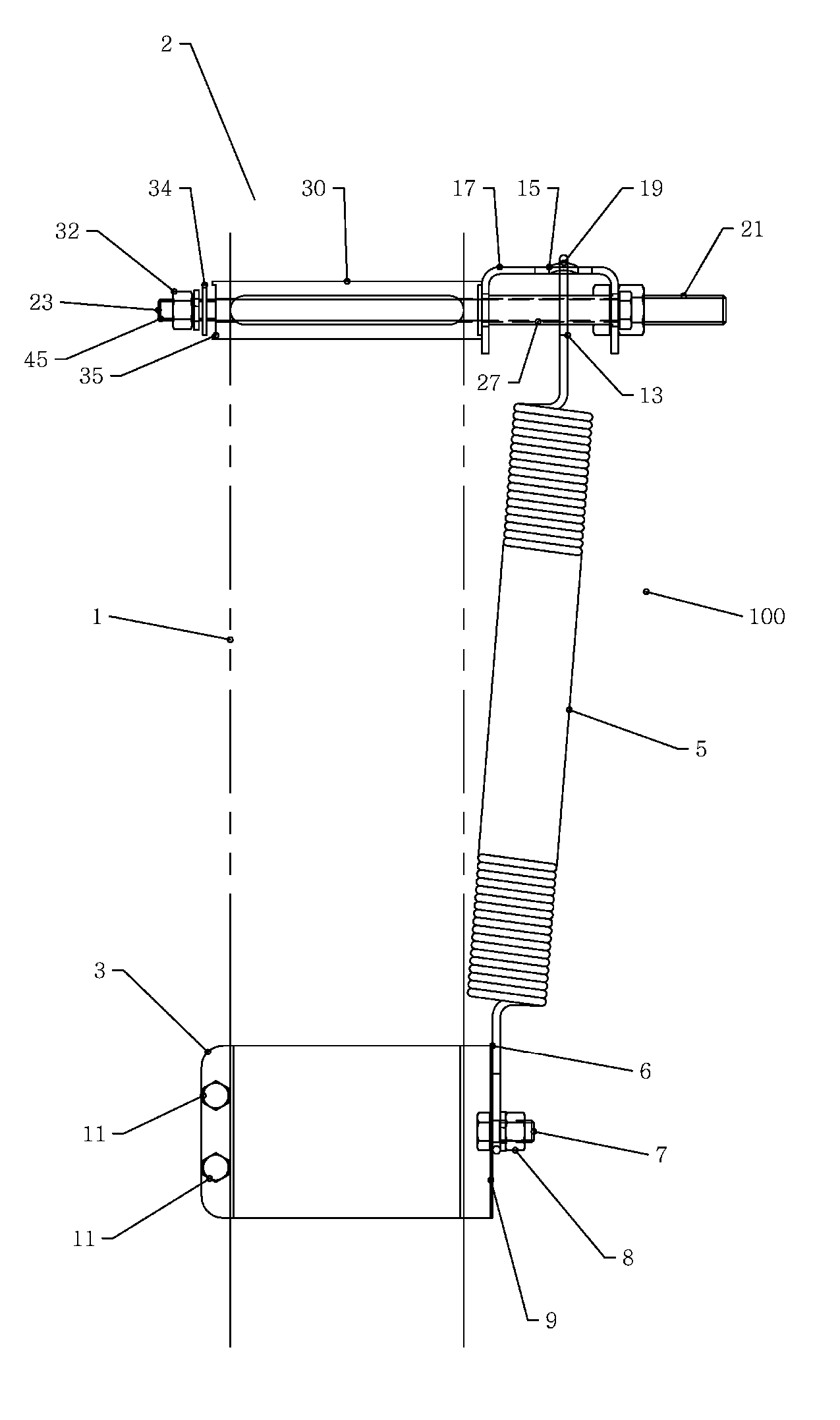
[0015] As shown in FIG. 1, a rigid line hanger 100 according to a first embodiment of the invention supports a rigid line 1 via a guide clamp assembly 2 coupled to a support clamp 3 by a spring 5. The spring 5 is secured at a first end 6 to the support clamp 3 via, for example, a spring bolt 7 and spring nut 8 connection to a spine 9 of the support clamp 3. The support clamp 3 may be secured to the rigid line 1 by one or more support clamp bolt(s) 11. Alternatively, the support clamp 3 may be any form of secure clamp, bracket or an existing connection point on the rigid line 1 for the first end of the spring 5.

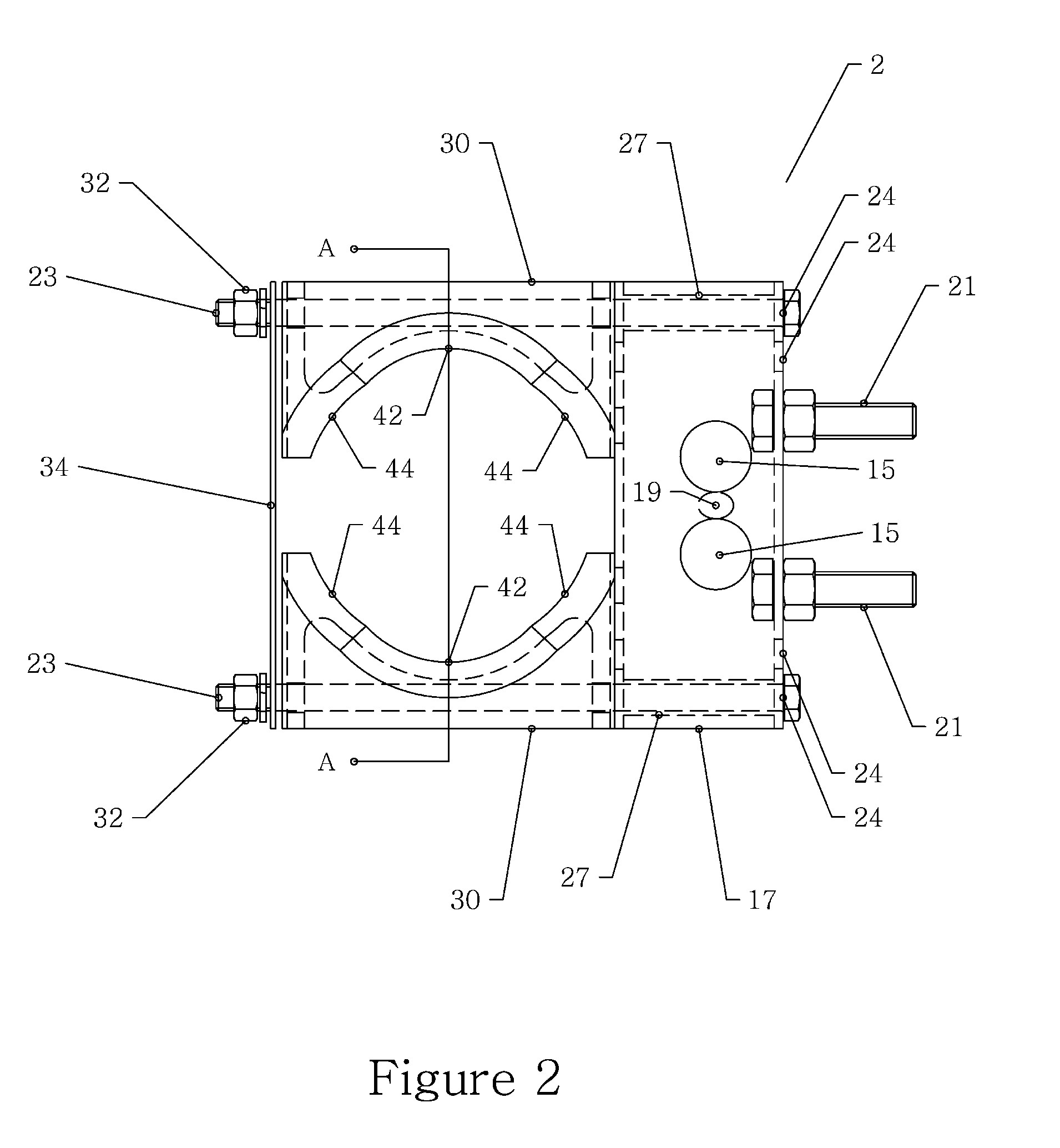
[0016] The spring 5 is attached at a second end 13 to the guide clamp assembly 2. The spring 5 attachment to the guide clamp assembly 2 may be, for example, via a hook formed in the second end 13 of the spring 5 that is looped through a pair of spring hole(s) 15 in a bracket 17. A spring mating surface 19 between the spring holes 15 may be machined or stamped to present a sha...


PUM


Abstract

A hanger for supporting a rigid line. The hanger having a bracket with a means for supporting a pair of, for example, plastic guides rotatable between a first position and a second position. The guides accepting the lateral insertion of the rigid line between them in the first position and restraining the rigid line from lateral movement in a second position. A retainer link operating to maintain the rigid line between the guides when in the first position and to lock the guide retainers into place when in the second position.

Description

BACKGROUND [0001] 1. Field of the Invention [0002] This invention relates to a hanger system for rigid lines and more particularly to a hanger system for rigid lines with multiple line diameter capability, manufacturing cost efficiencies and improved installation and service characteristics. [0003] 2. Description of Related Art [0004] Rigid lines, for example process piping or waveguides, are supported by hanger systems. A number of problems have been recognized when long rigid line runs are to be supported. For example, a typical RF transmission tower may vary in height from a few hundred to more than 1500 feet. A vertical run of a rigid line in the form of, for example, a circular, oval or square waveguide corresponding to the tower height must be erected and supported in the tower. Since the tower is made of steel and the waveguide is made of aluminum or copper, the waveguide tends to creep axially relative to the tower due to differential expansion accompanying changes in temper...

Claims


Application Information

Patent Timeline
Patent Type & Authority Applications(United States)
IPC IPC(8): F16L3/08
CPCF16L3/20F16L3/16
Inventor SHARMAN, DAVID
Owner ELECTRONICS RES
Why Eureka
Try Eureka