
Back projection-type screen and back projection-type projection device

Inactive Publication Date: 2007-08-02
KURARAY CO LTD
View PDF4 Cites 14 Cited by
  • Summary
  • Abstract
  • Description
  • Claims
  • Application Information

AI Technical Summary

Benefits of technology

[0073] The lens sheet is typically manufactured using a die. The die is generally produced by machining. The machining requires input of digitized design data into machining equipment. Most preferably, design data is an integral value. However, if an accurate value of design data contains several decimal places, a value which differs from the accurate value should be input due to the limitation to the number of digits to be input. Thus, a wide range of possible lens pitch values provides a large possibility to input an accurate value. The advantage of the present invention is significant in this aspect as well.
[0074] In the normal Fresnel lens 131 and the lenticular lens sheet 111 which includes the vertically fluted lenticular lenses 121, a curved moiré pattern is likely to occur at the center of the left and right ends of the screen. To avoid this, it is necessary to set the pitch ratio of the lenticular lenses 121 to about i+0.4 or i+0.6 (where i represents a natural number). For simplification of the description, it is assumed that the longitudinal direction of the lenticular lens 121 of the present invention is a vertical direction, and the optical center OC in FIG. 2 is located below the sheet.
[0075] According to the present invention, only a segment of a circular arc of the Fresnel lens 131 exists within the sheet and therefore there is no prism array which is parallel with the vertical direction unlike the normal Fresnel lens 131. Accordingly, it is possible to set the pitch ratio of the lens pitch P1 of the lenticular lens 121 and the lens pitch Pf of the Fresnel lens 131 not only to the known preferred range as disclosed in related arts but also to the range of i±0.35 or i+0.5±0.05 (where i represents a natural number), which cannot be set in related arts due to the occurrence of a strong moiré pattern. This effect is significant as the position of the optical center OC is away from the long side end, and preferably the optical center OC is distant from the center of the screen by 1.1 Lh or longer, more preferably 1.2 Lh or longer, and further preferably 1.3 Lh or longer, where Lh is the length of the short side.
[0076] Further, the combination of the lens pitch P1 of the lenticular lens 121 and the lens pitch Pf of the Fresnel lens 131 preferably satisfies the conditions given by any one of following equations (1) to (3). This suppresses the curved moiré pattern at the center of the left and right ends of the screen. P⁢ ⁢1Pf=i+0.0~0.35⁢ ⁢or⁢ ⁢P⁢ ⁢1Pf=1i+0.0~0.35(1)P⁢ ⁢1Pf=i+0.45~0.55⁢ ⁢or⁢ ⁢P⁢ ⁢1Pf=1i+0.45~0.55(2)P⁢ ⁢1Pf=i+0.65~1.0⁢ ⁢or⁢ ⁢P⁢ ⁢1Pf=1i+0.65~1.0(3)
[0077] Further, regarding the size of a pixel (PS) which is projected onto the screen and the lens pitch, each of PS / P1 and PS / Pf preferably satisfies:
[0080] 3.3 or above where j is 1 or 2, in order to suppress the moiré pattern due to interference among a pixel and the lens pitches P1 and Pf.

Problems solved by technology

Thus, the reflection loss of incident light occurs due to the diffusion material which is used to obtain a required viewing angle, which theoretically poses a limit to the achievement of high brightness screen and causes image blur.
Furthermore, the external light absorption layer 4 can only have a shape of parallel stripes theoretically, which poses a limit to obtained black area ratio.
However, the production of a fine 3D lens array sheet requires a highly accurate and large-scale die which is extremely difficult to produce.
If the external light absorption layer is formed on a different sheet from the lenticular lens sheet, the relative position of the sheets along the creepage can be misaligned, and it is thereby extremely difficult to accurately place the external light absorption layer at the non-light-transmission portion of the lenticular lens.
Further, the distance between the sheets can change due to temperature or humidity change to cause displacement of the lens focus position and thereby reduce the area of the external light absorption layer, which hampers the improvement of contrast or causes surface unevenness of the external light absorption layer.
Further, an increase in the number of lens sheets complicates the work of securing them to a television set frame.
Furthermore, if the sheets are transported with being secured to the television set frame, the sheets can be damaged due to the contact against each other.

Method used


Image

  • Back projection-type screen and back projection-type projection device
  • Back projection-type screen and back projection-type projection device
  • Back projection-type screen and back projection-type projection device

Examples


first embodiment

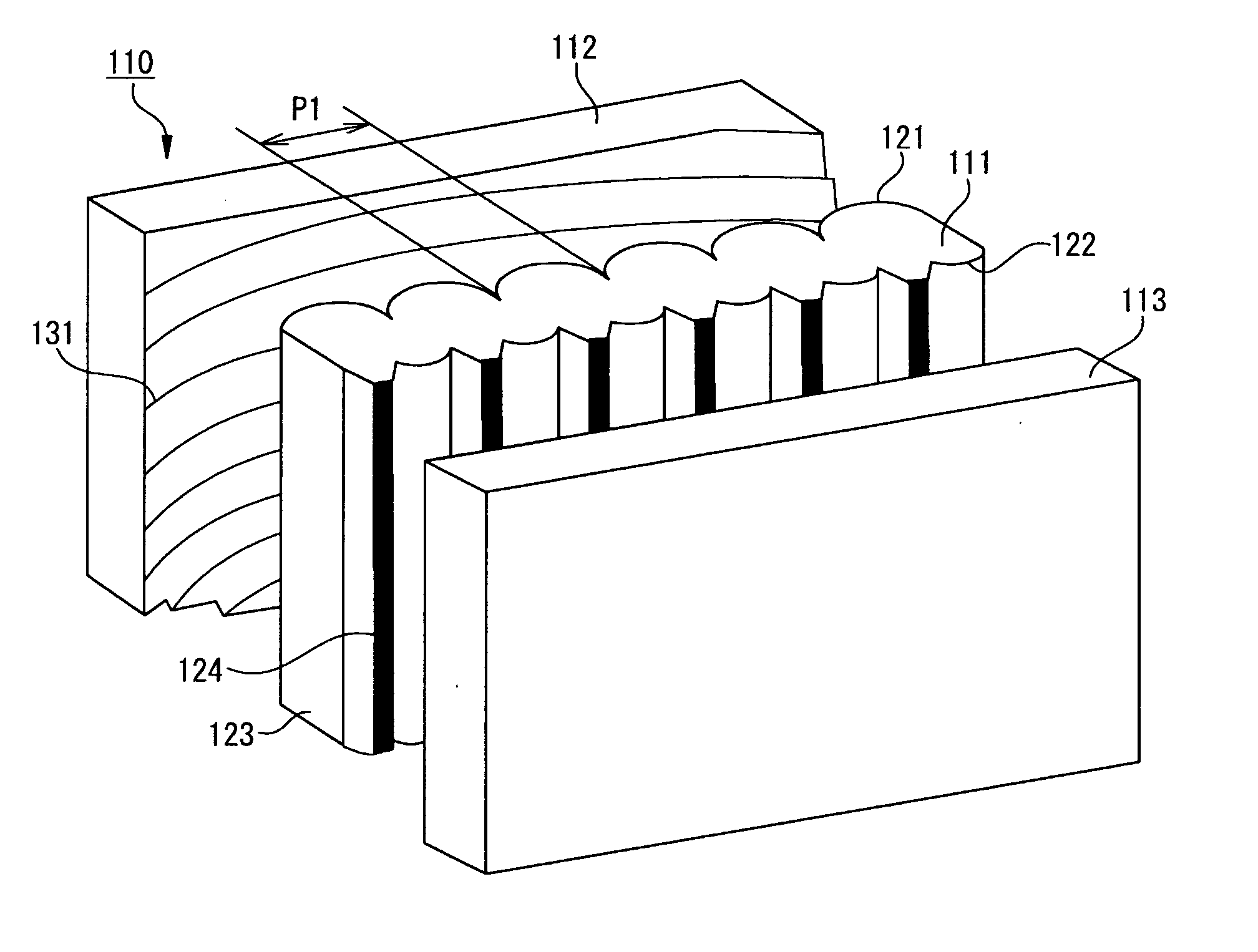
[0064]FIG. 1 is a perspective view showing a partial structure of a rear projection-type screen according to a first embodiment of the present invention. The rear projection-type screen 110 includes a lenticular lens sheet 111, a Fresnel lens sheet 112, and a front panel 113. The rear projection-type screen 110 is made up of the Fresnel lens sheet 112, the lenticular lens sheet 111, and the front panel 113 which are arranged in this order from the top to the bottom of the figure.

[0065] The lenticular lens sheet 111 is formed of a translucent substrate, on which a plurality of lenticular lenses 121 are formed on the surface on which projected light is incident. The lenticular lenses 121 are formed on the incident side of the surface through which the projected light is output from the lenticular lens sheet 111. Specifically, the lenticular lenses 121 are a plurality of convex lens arrays which are placed on the front side (incident side) when viewed from the light incident plane sid...

second embodiment

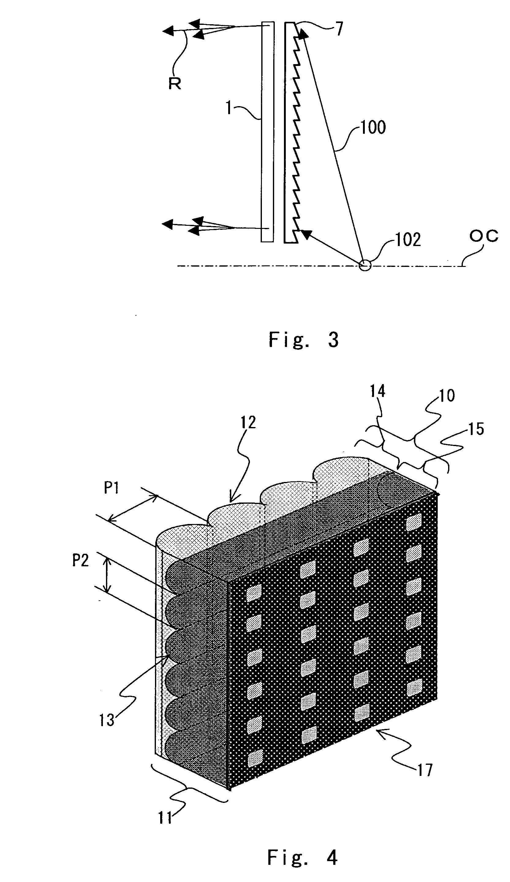
[0083]FIG. 4 is a perspective view showing the structure of a main part of a lenticular lens sheet according to a second embodiment of the present invention. In the following description regarding the lenticular lens sheet, the structure which does not include a self-aligned external light absorption layer 17 is referred to as a lenticular lens sheet A (which is denoted by the reference numeral “10”), and the structure which includes the lenticular lens sheet A and the self-aligned external light absorption layer 17 is referred to as a lenticular lens sheet B (which is denoted by the reference numeral “11”).

[0084] The lenticular lens sheet A is made up of a combination of a first lens layer 14 and a second lens layer 15 having different refractive indexes from each other which are integrated together with a second lens array 13 placed therebetween as an interface. In the second embodiment of the present invention, the refractive index of the first lens layer 14 is lower than the re...

third embodiment

[0125]FIG. 6 is a perspective view showing the structure of the main part of the lenticular lens sheet according to a third embodiment of the present invention.

[0126] The third embodiment is different from the second embodiment in the lenticular lens sheet A that a transparent base 21 is placed on the light exit side of the second lens layer 15 and the self-aligned external light absorption layer 17 is placed on the light exit surface of the transparent base 21. The other structure is the same as that of the second embodiment and thus not described herein.

[0127] The transparent base 21 may be an acrylic resin film, MS resin film, PET film, or the like.

[0128] Because the lenticular lens sheet according to the third embodiment of the present invention has the self-aligned external light absorption layer 17 on the light exit surface of the transparent base 21 which includes the first lens array 12 and the second lens array 13 arranged perpendicular to each other, the self-aligned ex...


PUM


Abstract

A rear projection-type screen and a rear projection-type projection device, in which contrast is enhanced, unevenness of an external light absorption layer is reduced, moiré trouble is suppressed, damage due to contact between sheets is suppressed, and the entire projection device can be reduced in size and weight. The rear projection-type screen is the so-called oblique projection system where the optical center of a Fresnel lens sheet 7 is located at a position outside a display screen area, above or below the screen. The lens array 12 of a lenticular lens sheet 1 is arranged substantially in the vertical direction. Moiré can be reduced by setting the pitch of Fresnel lens and the lens pitch of the lenticular lens sheet within a predetermined range.

Description

TECHNICAL FIELD [0001] The present invention relates to a rear projection-type screen and a rear projection-type projection device using a rear projection-type screen. BACKGROUND ART [0002] A rear projection-type screen that is used for a rear projection-type projection device or the like is typically made of two lens sheets which are laid out next to one another. A Fresnel lens sheet to narrow the image light from a rear projection-type projector to a certain range of angle is placed on the light source side, and a diffusion sheet to spread the image light transmitted through the Fresnel lens sheet to encompass an appropriate range of angle is placed on the observer's side. A lenticular lens sheet or an optical sheet as disclosed in Patent Document 1 is generally used as the diffusion sheet. A lenticular lens sheet for a rear projection-type screen as referred to in this specification includes a diffusion sheet which is provided with stripe or matrix optical units as shown in Paten...

Claims


Application Information

Patent Timeline
IPC IPC(8): G03B21/60
CPCG03B21/625G02B3/0068
Inventor ONO, YOUJI
Owner KURARAY CO LTD
Learn More