Method and apparatus for signal processing in RFID receivers

a technology of radio frequency identification and signal processing, applied in the field of telecommunications equipment, systems and methods, can solve the problems of high signal-to-noise ratio (snr), high signal-to-noise ratio, and the rfid communication channel is usually plagued by severe interference,

Inactive Publication Date: 2007-08-02
SYMBOL TECH INC
View PDF7 Cites 16 Cited by
  • Summary
  • Abstract
  • Description
  • Claims
  • Application Information

AI Technical Summary

Benefits of technology

[0017] In another aspect of the present invention, correlation coefficients are calculated between the received I / Q components and the reference signal within an interval shifted by a half-bit relative to the current bit interval. A two-bit interval is used to make a decision about each transmitted bit. Thus, a decision about a current bit is based on correlation coefficients computed for two adjacent bit intervals (the present bit interval, and the prior bit interval). This provides an energy gain with respect to conventional receiver implementations.

Problems solved by technology
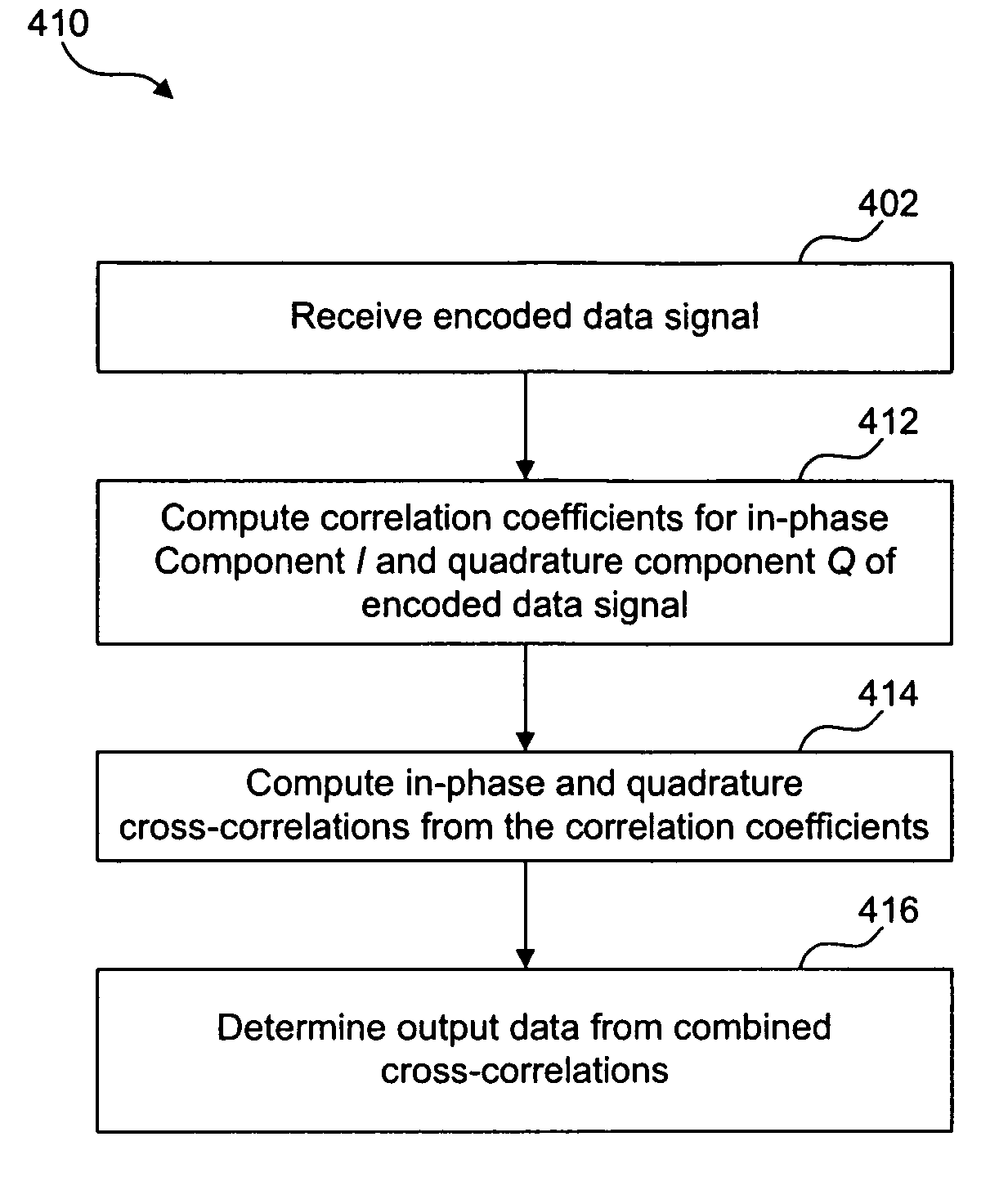
Development of reliable demodulation and decoding procedures for encoded signals is an important problem of all wireless system design, including wireless RFID systems.
A RFID communication channel is usually plagued with severe interference, multipath propagation, and fast fading, especially when a tag or / and a reader are moving.
A disadvantage of using the conventional incoherent algorithm in the FM0 mode is that one of the references does not have a zero mean, and, therefore, correlation of the received I / Q signal with this non-zero-mean replica does not remove a constant DC component of the I / Q transforms.
However, in a typical RFID environment, even after eliminating the DC component, the conventional incoherent algorithm can only achieve desired performance with a comparatively high signal-to-noise ratio (SNR) when the communication distance becomes relatively large.
Additionally, the requirement for two reference correlation channels for each quadrature component complicates receiver implementation.

Method used


Image

  • Method and apparatus for signal processing in RFID receivers
  • Method and apparatus for signal processing in RFID receivers
  • Method and apparatus for signal processing in RFID receivers

Examples


example rfid system embodiment

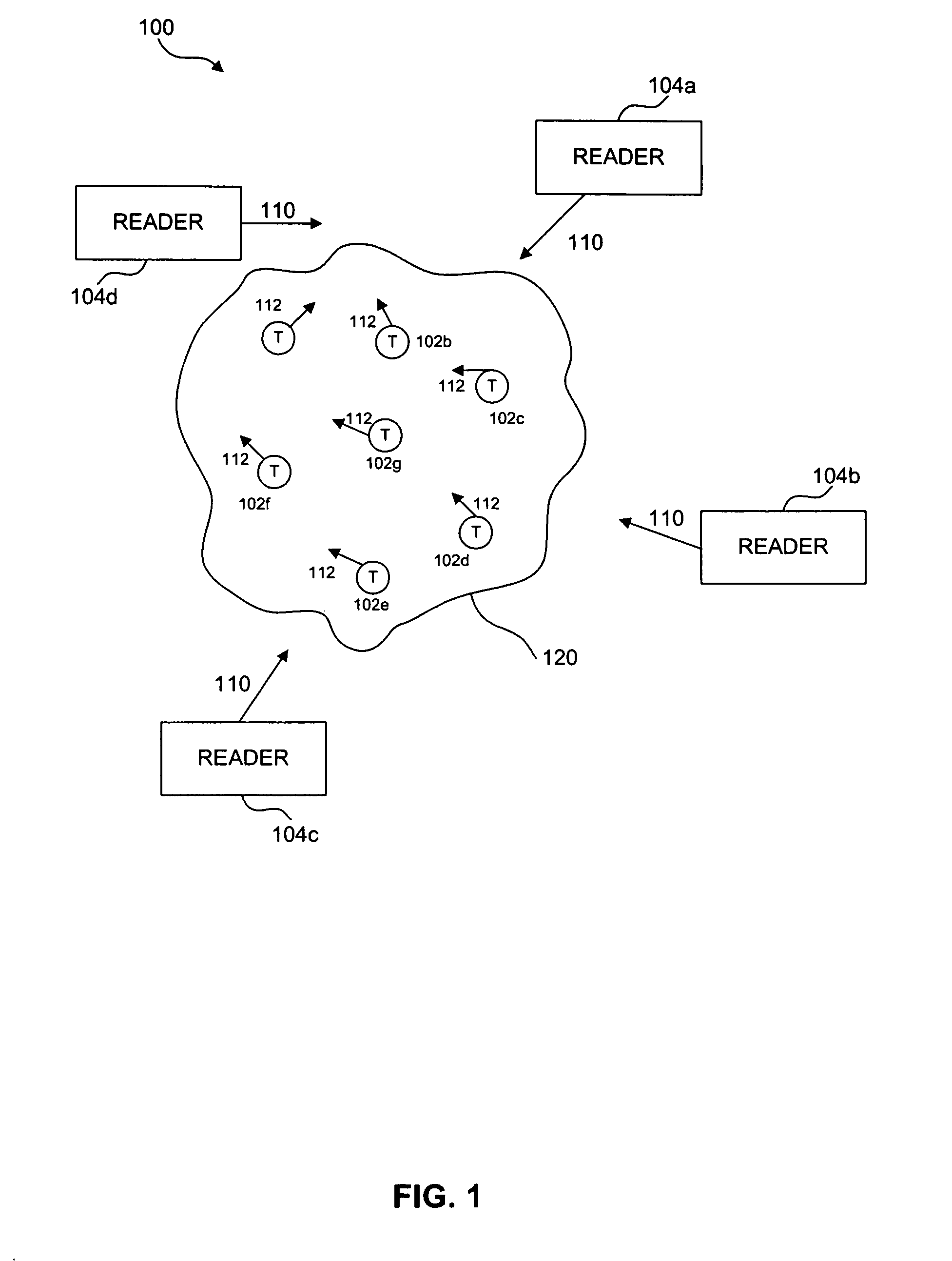
[0035]FIG. 1 describes an example environment 100, where the present invention may be implemented. Environment 100 includes a population 120 of RFID tags 102a-g, and RFID readers 104a-d. Readers 104a-d may operate independently, or may be connected together to form a reader network. Although not shown explicitly in FIG. 1, each of readers 104a-d is coupled to one or more antennas. When a reader 104 transmits an interrogation signal 110 through its corresponding antenna, one or more tags 102 respond by sending a signal 112 back to the reader. Signal 112 contains tag identification data, that can be decoded by the interrogating reader 104 in order to retrieve relevant information about an item to which tag 102 is attached, such as item price, item location etc.

reader embodiment

Example Conventional RFID Reader Embodiment

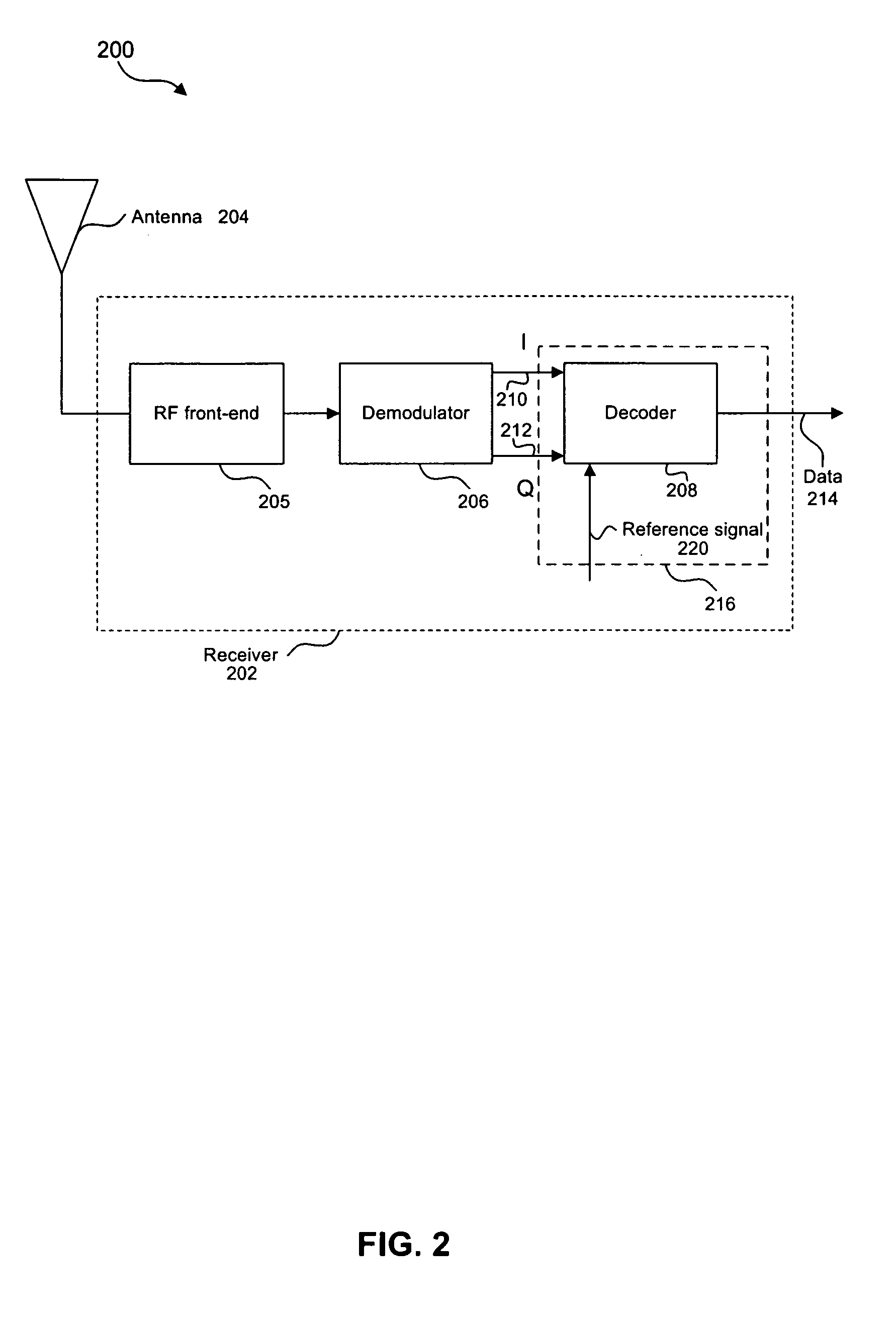
[0036]FIG. 2 shows an example block diagram of the receiver portion of a conventional RFID reader 200. Reader 200 typically includes one or more antennas 204, one or more receivers 202, one or more transmitters, one or more memory units, and one or more processors (transmitters, memory units, and processors are not shown in FIG. 2). As shown in the example of FIG. 2, receiver 202 includes a RF front-end 205, a demodulator 206, and a decoder 208. These components of reader 200 may include software, hardware, and / or firmware, or any combination thereof, for performing their functions, which are described in further detail in subsequent sections herein.

[0037] Antenna 204 is used for communicating with tags 102 and / or other readers 104. RF front-end 205 typically includes one or more of antenna matching elements, amplifiers, filters, an echo-cancellation unit, and / or a down-converter. In an embodiment, RF front-end 205 receives the tag respons...


PUM


Abstract

The present invention provides methods and apparatuses for demodulation and decoding of backscattered RFID tag signals, represented by their in-phase and quadrature components at the output of the demodulator in the receiver portion of a reader interrogator. Correlation coefficients for the in-phase and quadrature components of the received signal are calculated over a shifted bit interval. Performing a correlation over a shifted bit interval relative to the real bit interval allows the base-band receiver to involve a two-bit interval in making a decision about each transmitted bit. In contrast, in a conventional decoding algorithm, a single bit interval is involved in the decision-making process. Thus, the current method provides a 3 dB energy gain compared to the conventional method. A single zero-mean reference signal is used to compute correlation coefficients, eliminating constant components of the received signal, and simplifying digital implementation of the base-band receiver. A value of the output data is determined based on the combined correlation coefficients.

Description

BACKGROUND OF THE INVENTION [0001] 1. Field of the Invention [0002] The present invention relates generally to telecommunications apparatus, systems and methods. More specifically, the invention relates to Radio Frequency Identification (RFID) receivers that detect, demodulate and decode signals from RFID tags. [0003] 2. Background Art [0004] Radio frequency identification (RFID) technology is a wireless telecommunications technology where signal data is transmitted between various system elements via radio channels with variable parameters. [0005] In a RFID system, the presence of an RFID tag, and therefore the presence of the item to which the tag is affixed, may be checked and monitored wirelessly by devices known as “readers.” Readers typically have one or more antennas transmitting radio frequency signals to which tags respond. Since the reader “interrogates” RFID tags, and receives signals back from the tags in response to the interrogation, the reader is sometimes termed as “...

Claims


Application Information

Patent Timeline
Patent Type & Authority Applications(United States)
IPC IPC(8): H04L27/22H04B17/40
CPCH04L27/14
Inventor OKUNEV, YURIPOWELL, KEVIN J.
Owner SYMBOL TECH INC
Why Eureka
Try Eureka