Time-Space Multiplexed LADAR

a multiplexed laser and time-space technology, applied in the field of lasers, can solve the problems of difficult implementation of fiber lasers in laser systems, inability of lasers to generate the required power, and limited output power of fiber technology

Inactive Publication Date: 2007-08-02
THE STATE OF ISRAEL MINIST OF AGRI & RURAL DEV AGRI RES ORG ARO VOLCANI CENT
View PDF9 Cites 64 Cited by
  • Summary
  • Abstract
  • Description
  • Claims
  • Application Information

AI Technical Summary

Benefits of technology

[0029]There is also provided according to the teachings of the present invention, a fiber coupler comprising: (a) a primary optic fiber having a core and a clad, the clad having a first refractive index; and (b) a branch fiber forming an acute-angled junction with t...

Problems solved by technology

Unfortunately, this method requires high power laser in order to generate the required Signal Noise Ratio (SNR) in every pixel of the detector.Scanning system is based on partial illumination of the total Field Of Regard (FOR) by a smaller scanned FOV (in most cases a line illumination).
However, at some applications where long range is required the laser can not generate the required power.
Unfortunately, fiber technology is limited in term of output power.
Therefore, it is very difficult to implement fiber laser...

Method used


Image

  • Time-Space Multiplexed LADAR
  • Time-Space Multiplexed LADAR
  • Time-Space Multiplexed LADAR

Examples


Embodiment Construction

[0054]The present invention is a LADAR system and corresponding method.

[0055]The principles and operation of LADAR systems according to the present invention may be better understood with reference to the drawings and the accompanying description.

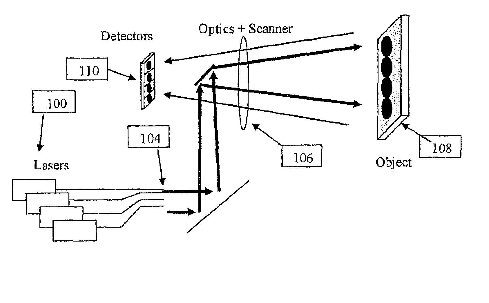
[0056]Before referring directly to the drawings, in general terms, the present invention provides a LADAR system including a detector optical arrangement defining a current optical field of view. An illumination subsystem is configured to transmit pulsed illumination at different times to each of a plurality of illumination sub-regions of the current optical field of view, and a detection subsystem, including one or more detectors, is deployed for detecting reflected illumination from a corresponding one or more detection sub-region of the current optical field of view. Each of the detection sub-regions overlaps a plurality of the illumination sub-regions, so that an overlap of each of the illumination sub-regions with the detection sub-reg...


PUM


Abstract

A LADAR system includes a detector optical arrangement defining a current optical field of view. An illumination subsystem without moving parts transmits pulsed illumination at different times to each of a number of illumination sub-regions of the current optical field of view, and a detection subsystem, including one or more detectors, detects reflected illumination from a corresponding one or more detection sub-region of the current optical field of view. Each of the detection sub-regions overlaps illumination sub-regions so that an overlap of each of the illumination sub-regions with the detection sub-region defines a LADAR image pixel of resolution finer than the detection sub-region.

Description

FIELD AND BACKGROUND OF THE INVENTION[0001]The present invention relates to LADAR and, in particular, it concerns a LADAR system in which illumination pulses are spatially and temporally distributed in order to achieve plural pixel resolution within an area sensed by a single detector.[0002]LADAR systems create 3D image of the an object or terrain by transmitting time varying light to various directions in their Field Of View (FOV) and measuring the time it took the light to reach the detector after being reflected. The result is effectively a surface map of the viewed scene, where each pixel value corresponds to a distance from the LADAR system to the object viewed. This will be referred to herein as a LADAR “image”.[0003]LADARS are designed according to two main architectures:[0004]Staring LADAR is based on a matrix of detectors that stare at the relevant Field Of View (FOV) and the illumination is performed by a pulsed laser that illuminate all the FOV instantaneously. Unfortunat...

Claims


Application Information

Patent Timeline
IPC IPC(8): G02B6/26G01S17/89
CPCG01S17/89G01S7/4815G01S7/4818G01S7/499
Inventor DANZIGER, YOCHAY
Owner THE STATE OF ISRAEL MINIST OF AGRI & RURAL DEV AGRI RES ORG ARO VOLCANI CENT
Why Eureka
Try Eureka