[0012]In view of the foregoing, embodiments of the present invention beneficially provide a system, program product, and method of manufacturing orthodontic appliances which can provide enhanced precision in forming a precision customized bracket slot in each bracket body of the orthodontic appliance. For example, according to embodiments of the present invention, bracket slot configurations can be formed that were not previously able to be formed. Further, according to embodiments of the present invention, a custom archwire and each of the precision custom bracket slots can form a high-precision archwire-bracket slot interface which can significantly reduce or minimize
torque error. Recognized by the Applicant is that use of
electrical discharge machining in conjunction with virtual bracket design, if employed to form the bracket slot in the bracket body, can provide enhanced precision and can allow for runner removal. Still further, according to an embodiment of the present invention, electrical discharge
machining in conjunction with virtual bracket design can provide enhanced precision and can allow for manufacturing process runner removal.
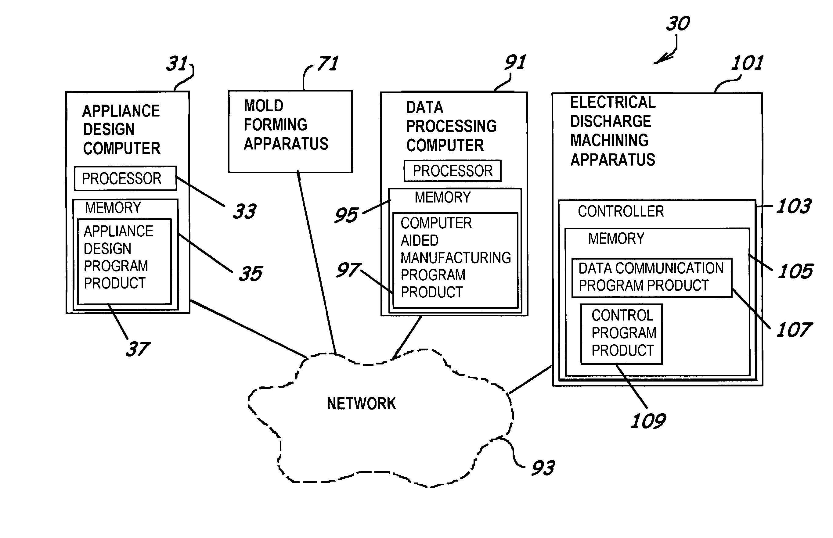
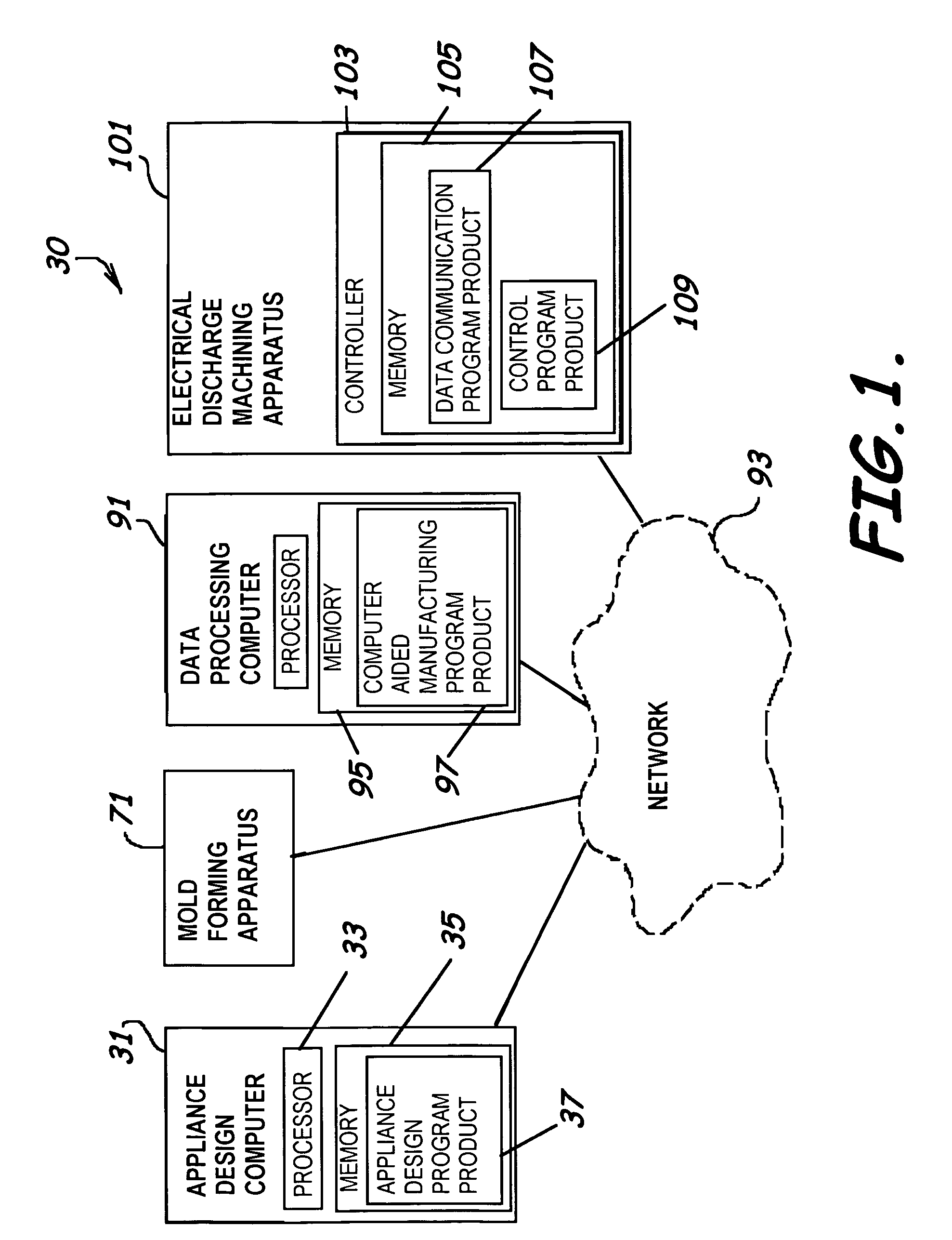
[0019]According to an embodiment of the present invention, a system to fabricate or manufacture orthodontic appliances can include a controller having memory, data communication program product stored in the memory including instructions to perform the operation of receiving electrical discharge device control instructions describing a virtual dimensional representation of a bracket slot in a bracket body of a bracket of an orthodontic appliance, and control program product also stored in the memory including instructions to perform the operation of deriving a
control signal carrying the electrical discharge device control instructions responsive to the electrical discharge device control instructions. The system can also include an electrical discharge device in communication with the controller having an electrical discharge
electrode assembly including an
electrode and having at least one drive section adapted to position the bracket body of a bracket in electrical discharge contact with the
electrode, responsive to the
control signal, to form the bracket slot according to a predefined electrical discharge
cutting pattern, for example, derived to substantially match associated dimensions of a preselected archwire. Beneficially, for example, this allows for the formation of an enhanced precision interface with the archwire.
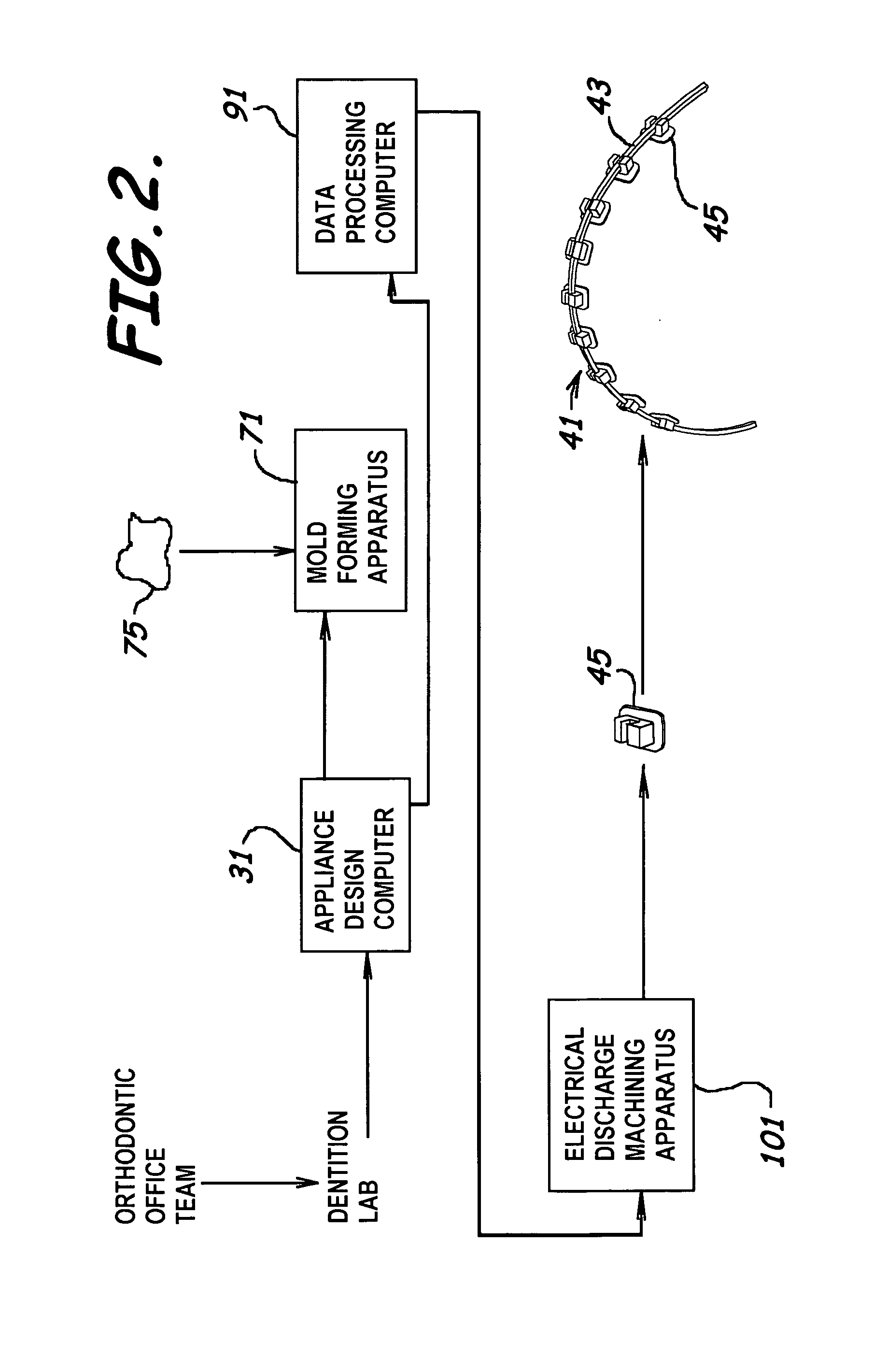
[0021]According to an embodiment of the present invention, a method of manufacturing an orthodontic appliance can include the step of deriving a control
signal carrying device control instructions from a virtual dimensional representation of a bracket slot in a bracket body of a bracket of an orthodontic appliance describing operations to execute an electrical discharge cutting pattern extending along a perimeter of the bracket slot and customized to substantially match associated dimensions of a preselected archwire. Beneficially, the result includes the formation of an enhanced precision interface with the archwire and a bracket slot having a closed perimeter to thereby define a bracket tube. The method can also include the step of executing the electrical discharge cutting pattern, responsive to a control
signal, to form the bracket tube.
[0024]Beneficially, embodiments of the present invention provide a manufacturing system and methods for manufacturing a highly-precise bracket slot, creating an
undercut in the sidewalls of the bracket slots, cutting an investment cast bracket off a runner, and cutting a highly precise tub into the bracket body. Embodiments of the present invention provide a manufacturing system for fabricating at least one design feature of an orthodontic appliance or a part thereof including a
data processing system deriving a control
signal carrying
machine control instructions from a virtual dimensional representation of the design feature and a manufacturing system fabricating the design feature that includes electrical discharge
machining, which can provide a level of precision and efficiency not otherwise available in systems not employing electrical discharge sheeting. Embodiments of the present invention relate to a manufacturing system and methods for manufacturing features of an orthodontic appliance or parts thereof utilizing electrical discharge
machining, which in an implementation of an embodiment provide for cutting a slot of a bracket with wire-
cut EDM technology such as, for example, the Mitsubishi wire EDM SX 10.

