Power transmission chain, power transmission device, and method of producing the chain

a technology of transmission chain and transmission device, applied in the direction of gearing, coupling device connection, mechanical apparatus, etc., can solve the problem of relatively high processing cost, achieve the effect of improving the strength reliability of the link, preventing excessive tensile stress, and ensuring the reliability of the link

Inactive Publication Date: 2007-08-02
JTEKT CORP
View PDF8 Cites 5 Cited by
  • Summary
  • Abstract
  • Description
  • Claims
  • Application Information

AI Technical Summary

Benefits of technology

[0015] In one insertion part, both of a pin and an interpiece are fitted so as to face a longitudinal direction of the chain, and either of them is fitted and fixed to the peripheral face of the insertion part of the link. The fitting and fixing are performed on edges (upper and lower edges) of a part orthogonal to the longitudinal direction of the insertion part. Conventionally, fitting conditions for the power transmission chain have not been considered, so strength reliability of the link has not been sufficient. However, by setting appropriate fitting conditions, it is possible to improve the strength reliability of the link. Fitting and fixing may be performed by any one of mechanical press-in, shrink-fitting and cool-fitting. Of course, the fitting conditions may define a difference in dimension (a half of the result of subtracting the up-and-down height of an insertion part from the up-and-down height of a pin or an interpiece), but by paying attention to stress, it is also possible to prevent the excessive tensile stress caused locally by making the maximum tensile stress to be predetermined stress or less or by assuring modification within the elastic limit. It is also achieved by defining a difference in dimension as well as defining stress in the periphery of the insertion part.
[0016] According to the power transmission chain of the present invention, it is possible to prevent excessive tensile stress from being caused locally when fitting, and to ensure strength of the links.
[0017] The power transmission chain described above is preferably so formed that one pin (interpiece) is shorter than the other pin (pin), and the end faces of the longer pin contact conical sheave faces of a pulley for a continuously variable transmission whereby power is transmitted by a frictional force caused by a contact thereof. Each pulley includes a fixing sheave having a conical sheave face and a movable sheave having a conical sheave face facing the sheave face of the fixing sheave, and a chain is interposed between the sheave faces of the both sheaves, and by moving the movable sheave by a hydraulic actuator, a winding radius of the chain varies corresponding to the distance between the sheave faces of the continuously variable transmission, whereby variable transmission can be performed continuously with smooth movement.
[0022] According to the method of manufacturing the power transmission chain of the present invention, a damage to be caused on a contact surface of pins when fitted is prevented. Further, since it is possible to insert pins into insertion parts in a state where links are laminated, assembling manhours can be reduced, and further the processing cost can be also reduced since end faces of pins can be processed not by forging but by grinding.
[0024] The end face shape of each pin (pin and interface) may be processed by grinding of course, but it may also be processed by forging. In forging, the diameter of an end face tends to be larger than other parts, so after shrink-fitting or cool-fitting has been completed, a pin and an interpiece are not subject to being fallen off, whereby reliability is further improved. Further, if the both ends have large diameters, mechanical press-in becomes more difficult, and an effect achieved by shrink-fitting or cool-fitting becomes larger. In addition, by using forging instead of grinding, the processing cost can be also reduced.
[0026] Further, it is preferable that shapes of end faces of pins and interpieces be formed by forging. Since it is required to cause a high load and a high frictional force in order to transmit torque (power) by a frictional force by contacting each sheave of a pulley with end faces of a pin, end faces of a pin must be in a predetermined shape. By forming them by forging, it is possible to reduce cost compared with the case of grinding.

Problems solved by technology

Further, assembling takes time since it is required to mechanically press-in a link one by one, and also an end face of a pin is processed not by forging but by grinding, so the processing cost may be relatively high.

Method used


Image

  • Power transmission chain, power transmission device, and method of producing the chain
  • Power transmission chain, power transmission device, and method of producing the chain
  • Power transmission chain, power transmission device, and method of producing the chain

Examples


Embodiment Construction

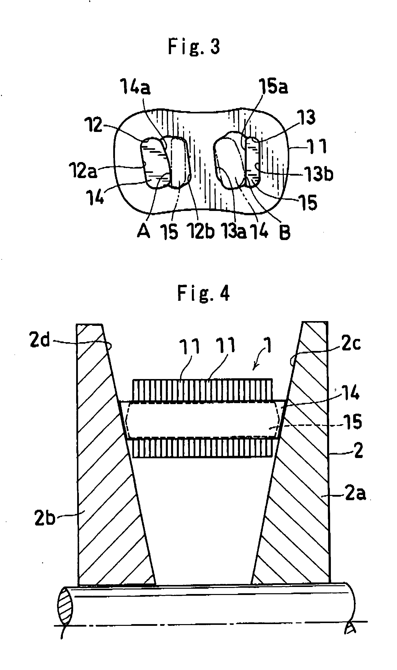
[0035] Hereinafter, an embodiment of the present invention will be explained with reference to the drawings. In the following explanation, up and down means up and down in FIG. 3.

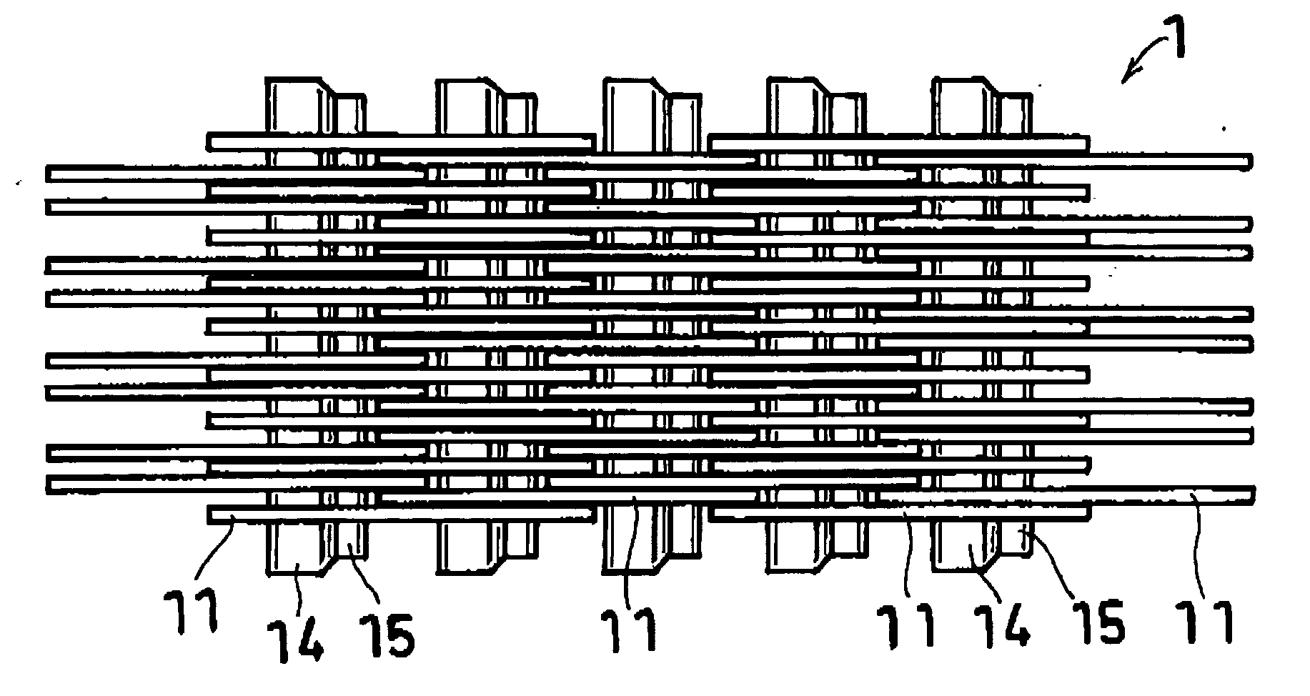
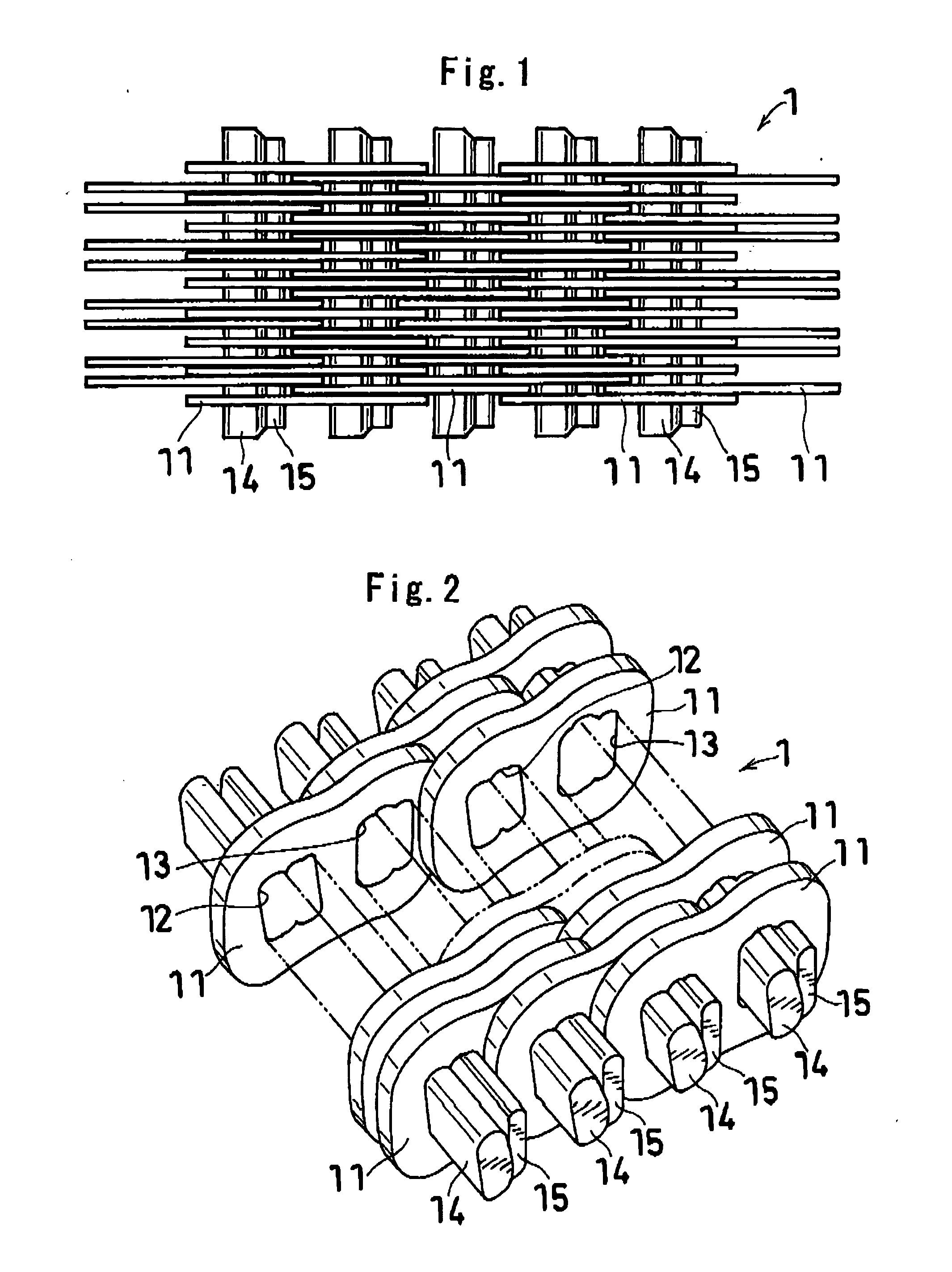
[0036]FIGS. 1 and 2 show a part of a power transmission chain manufactured according to the present invention. A power transmission chain (1) includes: a plurality of links (11) having front and back insertion parts (12) (13) provided with predetermined intervals in a chain length direction; and a plurality of pins (first pins) (14) and interpieces (second pins) (15) for connecting the links (11) aligned in a chain width direction so as to be bendable in a longitudinal direction (chain length direction).

[0037] As shown in FIG. 3, the front insertion part (12) includes a pin fixing part (12a) to which a pin (14) (shown by a continuous line) is fixed and an interpiece movable part (12b) in which an interpiece (15) (shown by an alternate long and two short dashes line) is movably fitted, and the back inserti...


PUM


Abstract

A power transmission chain 1 includes a plurality of links 11 having front and back insertion parts 12, 13 into which pins are inserted, and a plurality of pins 14 and a plurality of interpieces 15 for connecting the links 11 aligned in a chain width direction so as to be bendable in a longitudinal direction such that a front insertion part 12 of one link 11 and a back insertion part 13 of another link 11 correspond to each other. Each pin 14 and each interpiece 15 are fitted and fixed to the peripheral faces of the insertion parts 12, 13 by fitting, and a difference in dimension before the fitting is 0.005 mm to 0.1 mm.

Description

TECHNICAL FIELD [0001] The present invention relates to a power transmission chain, and more particularly, to a power transmission chain preferable for a continuously variable transmission (CVT) of an automobile and a power transmission device utilizing thereof, and a manufacturing method thereof. BACKGROUND ART [0002] As a continuously variable transmission for an automobile, as shown in FIG. 7, there has been known one which includes: a drive pulley (2) having a fixed sheave (2a) and a movable sheave (2b) and provided on the engine side; a driven pulley (3) having a fixed sheave (3b) and a movable sheave (3a) and provided on the drive wheel side; and an endless power transmission chain (1) provided over the both, and in which the movable sheaves (2b) (3a) are caused to come close to or leave away from the fixed sheaves (2a) (3b) by a hydraulic actuator, whereby a chain (1) is clamped by a hydraulic pressure so as to cause a contact load between the pulleys (2) (3) and the chain (1...

Claims


Application Information

Patent Timeline
Patent Type & Authority Applications(United States)
IPC IPC(8): H01R13/62F16G5/18
CPCF16H9/18F16G5/18
Inventor YASUHARA, SHINJIKAMAMOTO, SHIGEOFUKUI, NOBUKI
Owner JTEKT CORP
Why Eureka
Try Eureka