System for reducing carbon brake wear

a carbon brake and wear technology, applied in the field can solve the problems of increasing the complexity and cost of aircraft braking systems, increasing the cost of replacing stacks as a function of landing cycles between replacements, and most wear occurring during taxiing. the effect of carbon brake wear

Active Publication Date: 2007-08-02
HYDRO AIRE AEROSPACE CORP
View PDF31 Cites 5 Cited by
  • Summary
  • Abstract
  • Description
  • Claims
  • Application Information

AI Technical Summary

Benefits of technology

[0006] The present invention provides a relatively simple solution for reducing carbon brake wear. Rather than interfering with an existing brake control system, the device merely promotes a more wear-efficient use of the brakes by the pilot. By monitoring and displaying the number of times the brakes have been applied and their temperature, the pilot is encouraged to apply the brakes less often and / or maintain a preselected amount of heat in the brakes.

Problems solved by technology

While carbon brakes are preferred for weight and performance reasons over steel brakes, the cost of replacing the stack as a function of landing cycles between replacements is much higher than for steel brakes.
Consequently, most wear tends to occur during taxiing as the brakes may routinely be applied dozens of times in negotiating the taxiways between the runway and the gate and during the stop-and-go that may be encountered in the queue for take off.
Such systems add substantial complexity and cost to an aircraft braking system and retrofitting existing aircraft requires the expenditure of a significant amount of time and effort.

Method used


Image

  • System for reducing carbon brake wear
  • System for reducing carbon brake wear
  • System for reducing carbon brake wear

Examples


Embodiment Construction

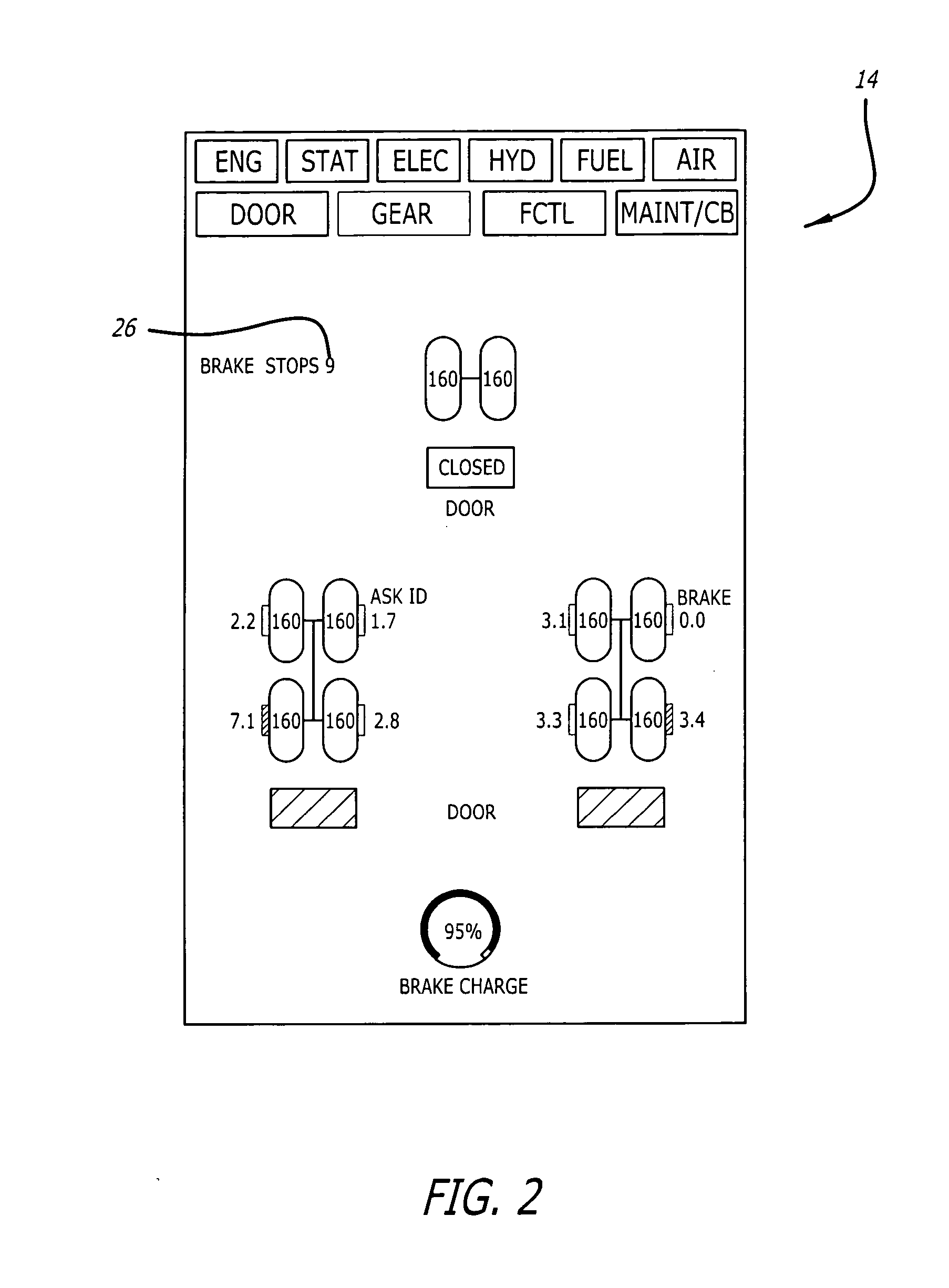
[0012] The present invention serves to promote a more wear-efficient use of an aircraft's carbon brakes to the extent it keeps the pilot apprised of how many times the brakes have been applied as well as of their temperature. Knowing that carbon brake wear is substantially a function of the number of times the brakes are applied, a pilot will be more inclined to reduce the number of brake applications while braking harder during each use if he is aware of the brake application count in real time. Additionally, knowledge of the brake temperature will encourage the pilot to maintain heat in the brakes and to thereby reduce the number of applications when the brakes are below a threshold temperature.

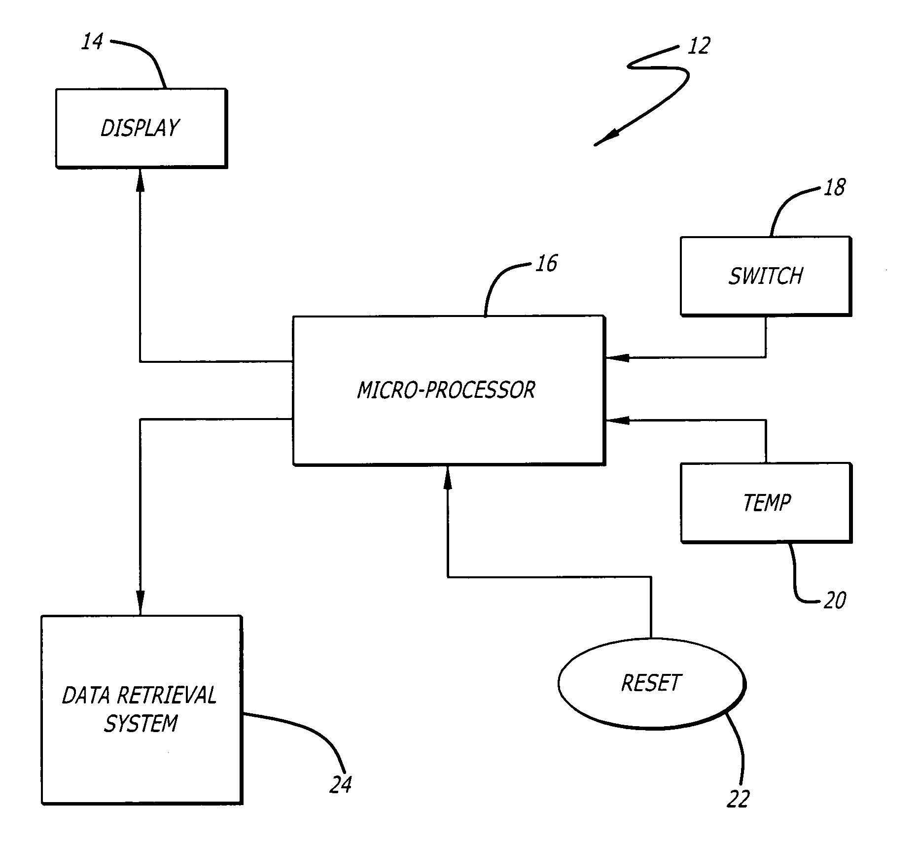
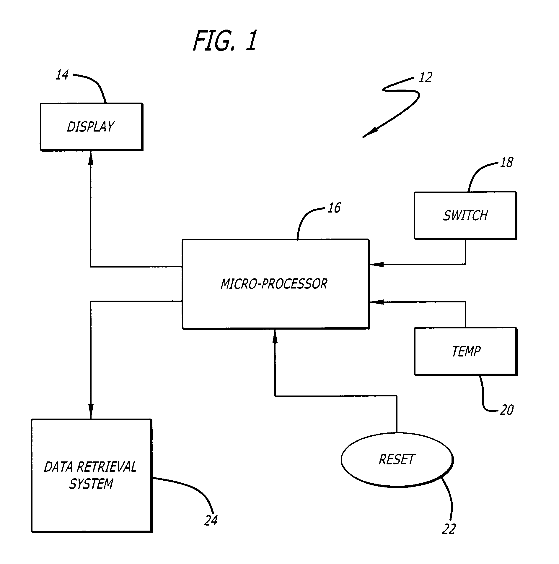
[0013]FIG. 1 is a schematic illustration of a preferred embodiment of the present invention. The system 12 includes a display component 14 that is positioned on the flight deck. The display receives information from a microprocessor 16 that in turn receives signals from a switch mechanism ...


PUM


Abstract

A brake monitoring system is described for use on aircraft having carbon brakes. The system displays the number of times the brakes have been applied in a preselected counting interval such as during each takeoff and landing cycle. By raising the pilot's awareness of the number of times the brakes have been applied, a more efficient brake use is encouraged in view of the knowledge that carbon brake wear is substantially a function of the number of applications rather than the total energy that is converted thereby. Additionally, the monitoring system provides an indication of the temperature of the brakes which encourages the pilot to maintain a minimum temperature therein beyond which wear is reduced.

Description

FIELD OF THE INVENTION [0001] The present invention generally relates to aircraft braking systems and more particularly pertains to efforts to reduce carbon brake wear. BACKGROUND OF THE INVENTION [0002] Carbon brakes as are fitted to many modem aircraft that are designed to carry large passenger or cargo payloads. Such brakes rely on the use of a carbon composite material to serve as friction material as well a heat sink. A stack of carbon rotor disks and carbon stator disks are coaxially arranged in an alternating sequence along a wheel's axis wherein the rotor disks are rotationally keyed to the wheel while the stator disks are keyed to the stationary axle. Braking force is generated by the pressurization of piston actuators that are configured to compress the stack between a pressure plate and a backing plate to thereby cause the friction surfaces of adjacent disks to engage one another. While carbon brakes are preferred for weight and performance reasons over steel brakes, the ...

Claims


Application Information

Patent Timeline
Patent Type & Authority Applications(United States)
IPC IPC(8): G01C5/00G06F19/00
CPCB60T8/00B60T17/221B60T17/18
Inventor DEVLIEG, GARYGOWAN, JOHN
Owner HYDRO AIRE AEROSPACE CORP
Why Eureka
Try Eureka