Air conditioning system

a technology of air conditioning system and air conditioner, which is applied in the field of air conditioning system, can solve the problems of reducing the coefficient of performance (cop), not achieving sensible heat load, increasing the number of parts to be maintained, and increasing the cost and cos

Inactive Publication Date: 2007-08-09
DAIKIN IND LTD
View PDF3 Cites 26 Cited by
  • Summary
  • Abstract
  • Description
  • Claims
  • Application Information

AI Technical Summary

Benefits of technology

[0062] In this air conditioning system, at system startup, before starting the operation in which the latent heat load in the room is preferentially treated according to any one of the nineteenth to the twenty-second aspects of the present invention, the necessity to start such an operation is determined based on the absolute humidity of the room air. Accordingly, at system startup, the operation in which the latent heat load in the room is preferentially treated is prevented from being unnecessarily performed, and therefore the normal operation in which the latent heat load and the sensible heat load in the room are treated can be initiated as soon as possible.

Problems solved by technology

Consequently, the difference between high and low pressures in the vapor compression refrigeration cycle increases and so does the power consumption of the compressor, resulting in a reduced coefficient of performance (COP).
Therefore, this dehumidifier can treat the latent heat load in the room but not the sensible heat load, which has been a problem.
However, in such a large scale air conditioning system, a plurality of air conditioners each comprising an adsorbent heat exchanger are needed, so that several compressors and the like to be used as heat sources may need to be installed according to the number of the adsorbent heat exchangers, which consequently creates problems such as an increase in cost and an increase in the number of parts to be maintained.
Further, since excessive refrigerant is produced in the refrigerant circuits of each air conditioner because of the increase or decrease in the amount of circulating refrigerant along with a change in the operating load of the air conditioning system, receivers to accumulate excessive refrigerant that is produced along with the decrease in the amount of circulating refrigerant need to be connected according to the number of adsorbent heat exchangers, which causes further increase in cost and in size of an unit into which the adsorbent heat exchanger is built.

Method used


Image

  • Air conditioning system
  • Air conditioning system
  • Air conditioning system

Examples


first embodiment

(1) Configuration of the Air Conditioning System

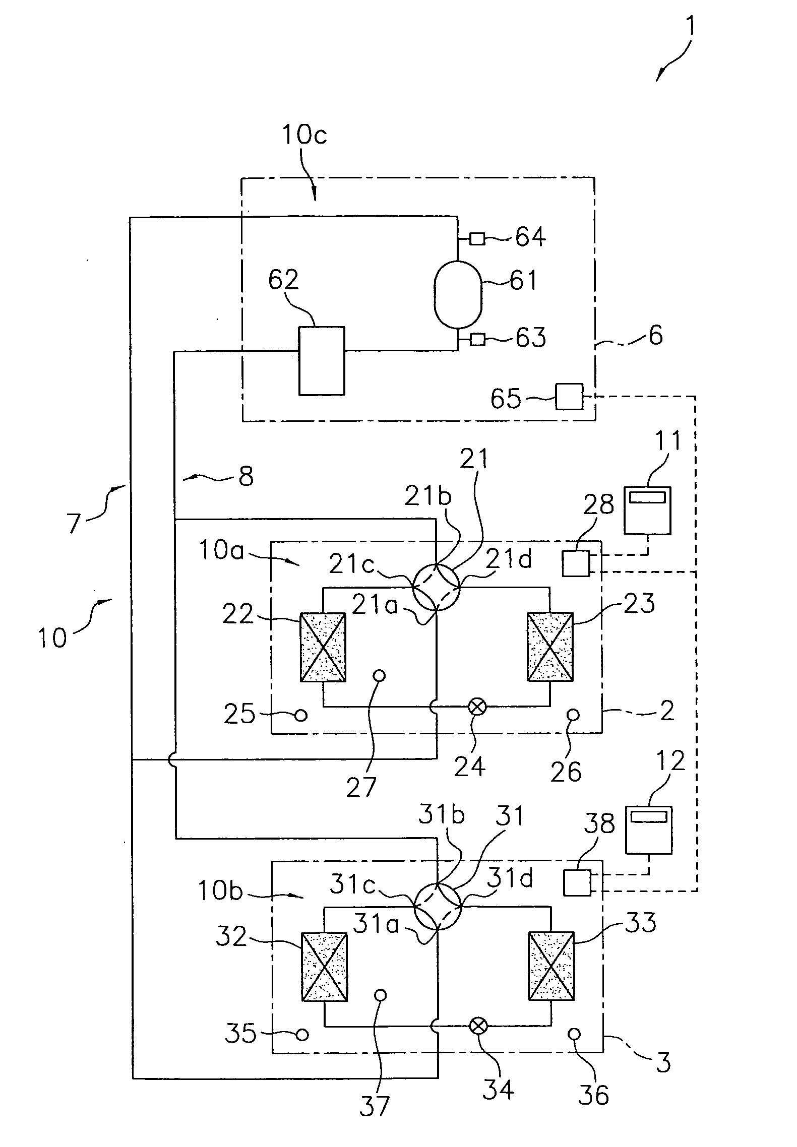
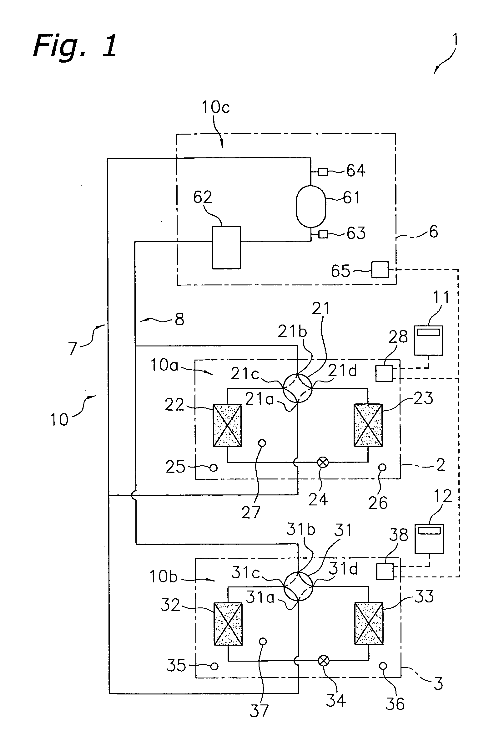
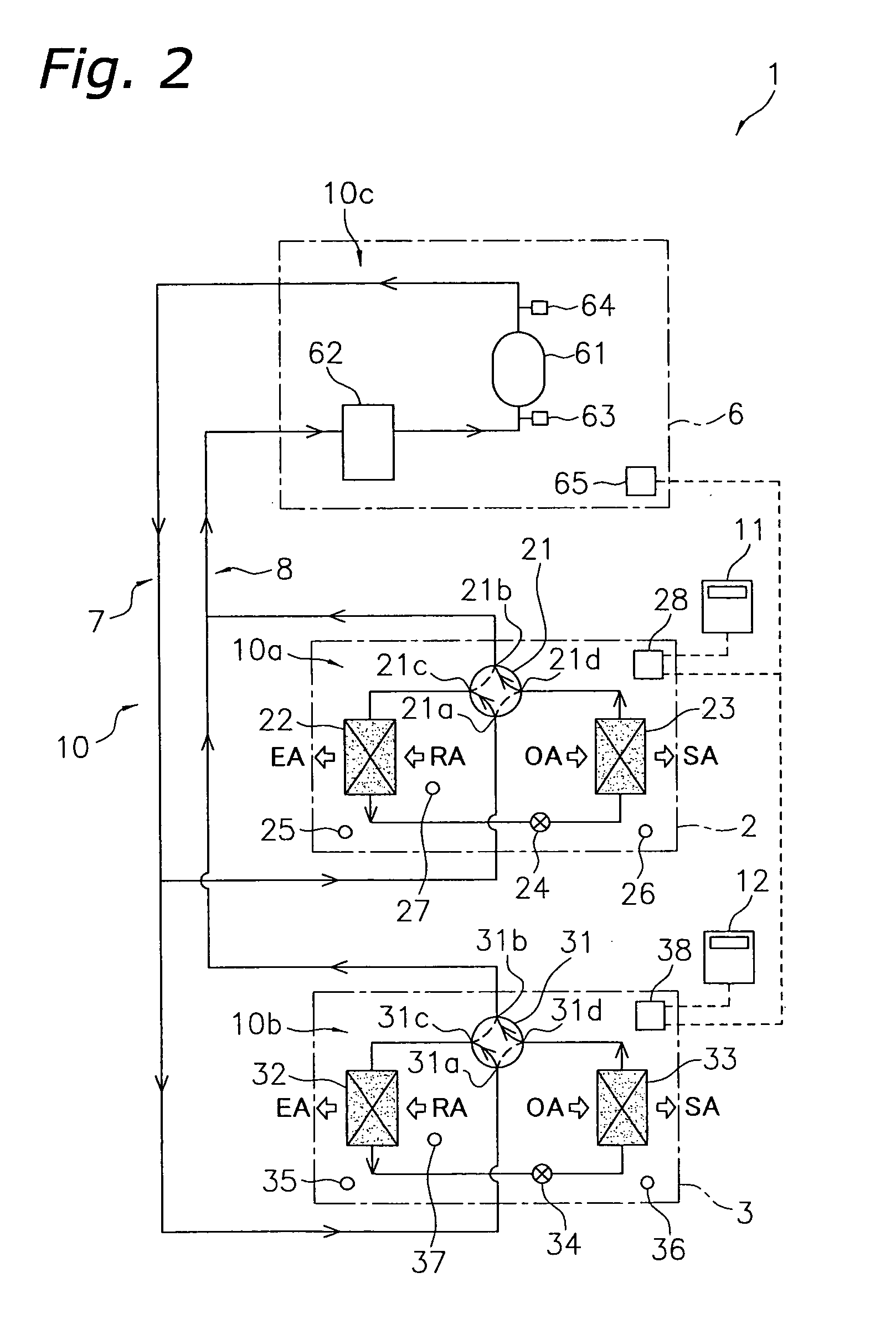
[0132]FIG. 1 a schematic diagram of a refrigerant circuit of an air conditioning system 1 of a first embodiment according to the present invention. The air conditioning system 1 is an air conditioning system that treats the latent heat load and the sensible heat load in the room of a building and the like by operating a vapor compression type refrigeration cycle. The air conditioning system 1 is so-called separate type multi air conditioning system, and mainly comprises: a plurality (two in this embodiment) of utilization units 2, 3; a heat source unit 6; and connection pipes 7, 8, which connect the utilization units 2, 3 to the heat source unit 6. In the present embodiment, the heat source unit 6 functions as a heat source that is shared by the utilization units 2, 3. In addition, although the present embodiment has only one heat source unit 6, a plurality of heat source units 6 may be connected in parallel when there are many utiliz...

second embodiment

(1) Configuration of the Air Conditioning System

[0220]FIG. 23 is a schematic diagram of a refrigerant circuit of an air conditioning system 101 of a second embodiment according to the present invention. The air conditioning system 101 is an air conditioning system that treats the latent heat load and the sensible heat load in the room of a building and the like by operating a vapor compression type refrigeration cycle. The air conditioning system 101 is so-called separate type multi air conditioning system, and comprises: a latent heat load treatment system 201 that mainly treats the latent heat load in the room; and a sensible heat load treatment system 301 that mainly treat the sensible heat load in the room.

[0221] The configuration of the latent heat load treatment system 201 is the same as that of the air conditioning system 1 of the first embodiment. Therefore, all reference numerals representing each component of the utilization unit 2 of the first embodiment will be changed...

third embodiment

(1) Configuration of the Air Conditioning System

[0335]FIG. 32 a schematic diagram of a refrigerant circuit of an air conditioning system 401 of a third embodiment according to the present invention. The air conditioning system 401 is an air conditioning system that treats the latent heat load and the sensible heat load in the room of a building and the like by operating a vapor compression type refrigeration cycle. The air conditioning system 401 is so-called separate type multi air conditioning system, and mainly comprises: a latent heat load treatment system 201 that mainly treats the latent heat load in the room; and a sensible heat load treatment system 501 that mainly treat the sensible.

[0336] Since the configurations of the latent heat load treatment system 201 is the same as that of the latent heat load treatment system 201 of the second embodiment, a description of each component thereof will be omitted.

[0337] The sensible heat load treatment system 501 is different from ...


PUM


Abstract

An air conditioning system to treat a latent heat load and a sensible heat load in a room includes a plurality of utilization units, a heat source unit, and connection pipes that connect between the units. The utilization units include adsorbent heat exchangers provided with an adsorbent on the surface of each. The utilization units are configured to alternate between an adsorption process and a regeneration process. The heat source unit includes a compression mechanism and an accumulator.

Description

TECHNICAL FIELD [0001] The present invention relates to an air conditioning system. More specifically, the present invention relates to an air conditioning system in which the latent heat load and the sensible heat load in the room are treated by operating a vapor compression refrigeration cycle. BACKGROUND ART [0002] Conventionally, air conditioners that cool and dehumidify the room are known (for example, see Patent Document 1). This type of air conditioner comprises a vapor compression refrigerant circuit having an outdoor heat exchanger as a heat source side heat exchanger and an indoor heat exchanger as an air heat exchanger, and a refrigerant is circulated in this refrigerant circuit to operate a refrigeration cycle. This air conditioner dehumidifies the room by setting the evaporation temperature of the refrigerant in the indoor heat exchanger lower than the dew point temperature of the room air and thus condensing moisture in the room air. [0003] Also, dehumidifiers comprisi...

Claims


Application Information

Patent Timeline
Patent Type & Authority Applications(United States)
IPC IPC(8): F25D17/06F25D23/00F25B17/08F24F3/14F24F5/00F24F11/02F24F11/76F25B13/00
CPCF24F3/065F24F3/1411F24F3/1429F25B2313/023F25B13/00F24F2110/12F24F11/41F24F2003/1458
Inventor FUJIYOSHI, RYUSUKEYABU, TOMOHIRO
Owner DAIKIN IND LTD
Why Eureka
Try Eureka