Roll-former apparatus with rapid-adjust sweep box

a technology of rolling-former and sweep box, which is applied in the direction of metal rolling, metal rolling arrangement, manufacturing tools, etc., can solve the problems of increasing in-process inventory, increasing dimensional variability, and adding cos

Active Publication Date: 2007-08-09
SHAPE CORP
View PDF39 Cites 41 Cited by
  • Summary
  • Abstract
  • Description
  • Claims
  • Application Information

AI Technical Summary

Benefits of technology

[0015] In a narrower form, the external mandrels include one or more additional layer

Problems solved by technology

However, secondary operations add cost, increase dimensional variability, and increase in-process inventory, and also present quality issues.
Nonetheless, it is important to understand that bumper beams for modern vehicles present a substantial increase in difficulty due to their relatively large cross-sectional size and non-circular cross-sectional shape, the high strength of materials used herein, the very tight dimensional and tolerance requirements of vehicle manufacturers, the cost competitiveness of the vehicle manufacturing industry, and the high speed at which modern roll-forming lines run.
However, even though the sweep station is adjustable, it does not necessarily mean that the apparatus is able to manufacture beams having multiple sweep radii therein.
Certainly, non-uniform longitudinal curvatures cannot be uniformly repeated formed along a length of a continuous beam by manual means and further cannot productively and efficiently be made in high speed rollforming operations using slow-acting automated equipment.
Further, there is no teaching in the '451 patent to form a multi-swept beam using a computer controlled sweep apparatus in continuation with a coordinated computer-controlled cut-off device adapted to cut off individual bumper beam sections from the continuous beam at specific locations related to particular sweep regions.
Further, based on the density of threads suggested by the FIGS. 1-2 (and also based on the lack of any discussion in the '451 patent regarding automated “cyclical” adjustment), it appears that the device of the '451 patent suffers from the same problem as manually adjustable sweep stations—i.e., that it cannot

Method used


Image

  • Roll-former apparatus with rapid-adjust sweep box
  • Roll-former apparatus with rapid-adjust sweep box
  • Roll-former apparatus with rapid-adjust sweep box

Examples


Embodiment Construction

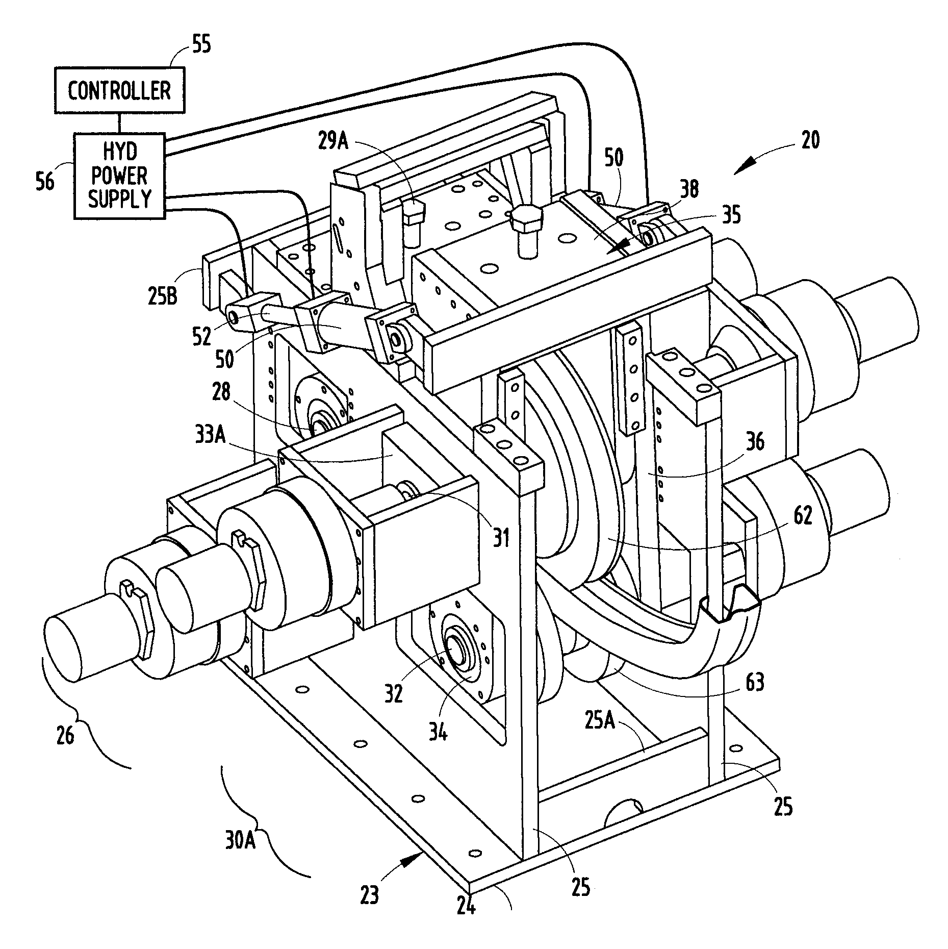
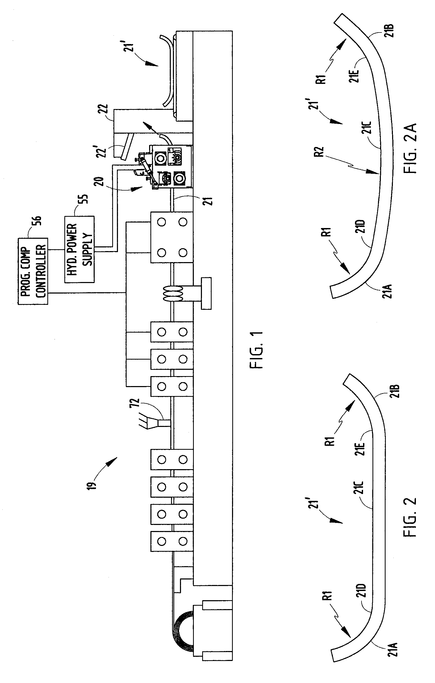
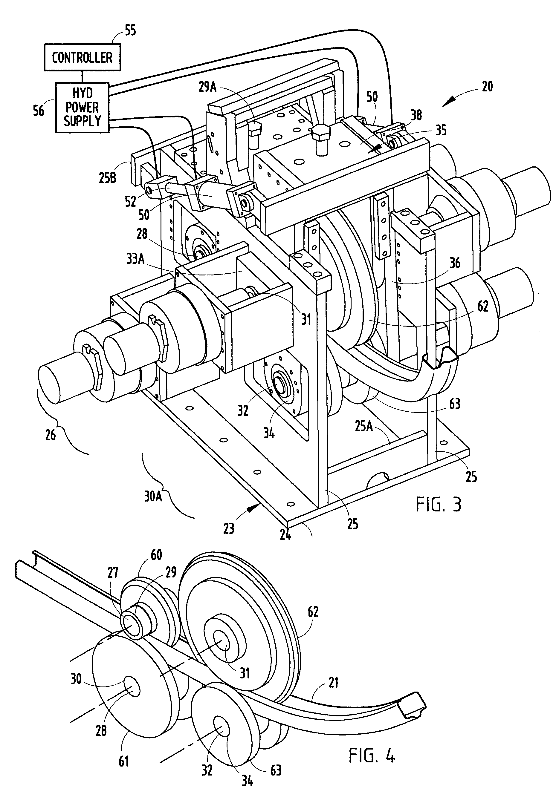
[0032] The present roll-former mill apparatus 19 (FIG. 1) includes a auto-variable sweep station 20 adapted to make roll-formed vehicle bumper beams 21′ (also called “bumper beam segments” or “reinforcement beams” herein) having a constant cross-sectional shape, but having a varied longitudinal curvature formed by the sweep station 20. The sweep station 20 is positioned in-line with and at an output end of the roll-former apparatus 19. The roll-forming portion of the apparatus 19 is not unlike that shown in FIG. 4 of Sturrus U.S. Pat. No. 5,092,512, and the teachings of the Sturrus '512 patent are incorporated herein in their entirety. The present sweep station 20 includes a multi-roller system that is computer-controlled and automated. The sweep station permits quick and accurate adjustment in sweep radii, allowing the sweeping operation to be repeatedly varied during the roll-forming process. By this arrangement, dissimilar sweep radii can be repeatedly and accurately formed along...


PUM

PropertyMeasurementUnit
Speedaaaaaaaaaa
Shapeaaaaaaaaaa
Radiusaaaaaaaaaa

Abstract

A computer controlled roll-forming apparatus is adapted to provide a repeating pattern of different longitudinal shapes to a continuous beam “on the fly” during the roll-forming process. A sweep station of the apparatus includes a primary bending roller tangentially engaging the continuous beam along the line level and an armature for biasing the continuous beam against the primary bending roller for a distance partially around a downstream side of the primary bending roller to form a sweep. Actuators adjustably move the armature partially around the downstream side of the primary bending roller between multiple positions for imparting a series of different longitudinal shapes. Internal and external mandrels control wall stability to allow even sharper sweeps. In one form, the apparatus also includes a coordinated cut-off, so that when separated into bumper beam segments, the ends of the individual beam segments have a greater sweep than their center sections.

Description

[0001] This is a continuation-in-part of co-assigned application Ser. No. 11 / 150,904, filed Jun. 13, 2005, entitled ROLL-FORMER APPARATUS WITH RAPID-ADJUST SWEEP BOX.BACKGROUND [0002] The present invention relates to a roll-forming apparatus with a sweep station adapted to impart multiple sweeps (i.e., non-uniform longitudinal curvatures) into a roll-formed beam as part of a continuous in-line process. [0003] Roll-formed bumper beams have recently gained wide acceptance in vehicle bumper systems due to their low cost and high dimensional accuracy and repeatability. Their popularity has increased due to the ability to sweep (i.e., provide longitudinal curves) in the roll-formed beam sections in order to provide a more aerodynamic appearance. For example, one method for roll-forming a constant longitudinally curved beam is disclosed in Sturrus U.S. Pat. No. 5,092,512. [0004] The aerodynamic appearance of vehicle bumpers is often further enhanced by forming a section of the front surfa...

Claims


Application Information

Patent Timeline
IPC IPC(8): B21B15/00
CPCB21D7/028B21D5/08
Inventor LYONS, BRUCE W.GOULD, BRYAN E.DODD, JAMES H.HEINZ, RICHARD D.
Owner SHAPE CORP
Why Eureka
Try Eureka