Method of transporting and storing wind generated energy using a pipeline

a technology of wind generated energy and pipeline, which is applied in the direction of electric generator control, machine/engine, greenhouse gas reduction, etc., can solve the problems of increasing the cost of electrical transmission lines, and increasing the cost of constructing electrical transmission lines, so as to reduce the cost, reduce the cost, and increase the economic effect of installing the pipeline system

Active Publication Date: 2007-08-09
ENIS BEN M +1
View PDF41 Cites 57 Cited by
  • Summary
  • Abstract
  • Description
  • Claims
  • Application Information

AI Technical Summary

Benefits of technology

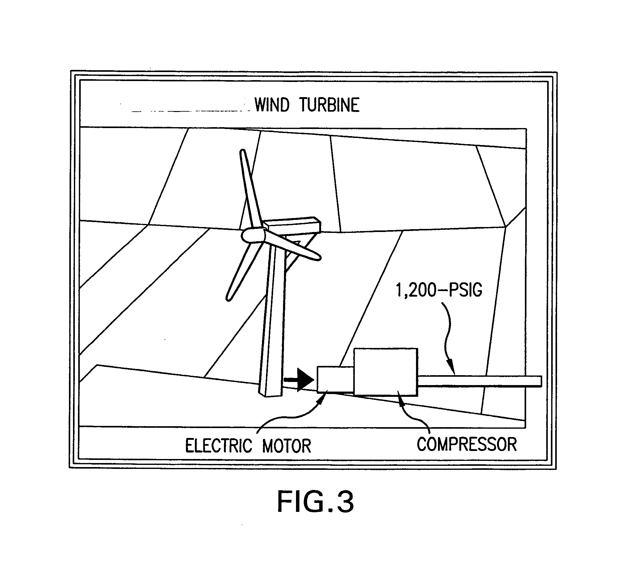
[0036] One aspect of the present invention relates to the use of a pipeline system (either aboveground or underground) into which the compressed air from the wind turbines can be distributed, wherein the pipeline can be used to not only store the compressed air, but also transport the compressed air energy from one remote location (such as where wind conditions are ideal) to where the energy is needed (a facility or community in need of the power). Storage of compressed air in this manner allows the energy derived from the wind to be stored for a period of time until it is needed. The pipeline can also be used as a means of transporting the stored energy, such as from where the wind farm is located, to the location where the energy is needed, wherein the pipeline itself can serve as both storage and transport means.
[0037] A benefit to using this type of system is that the transmission means, which in this case is a pipeline, has the ability to not only transport energy from one location to another, but also to store energy. This way, unlike conventional power lines, which can only transmit power through a conduit, a predetermined amount of energy can be stored so that energy will be available, even if energy at the source becomes temporarily unavailable, i.e., the wind stops blowing, or the utility shuts down. It can also store energy produced during low demand periods, such as at night, so that it can be distributed and used during high demand periods, when the energy rates are higher. In such case, the system will be able to continue to supply energy to the end user for a predetermined amount of time, at a lower cost.
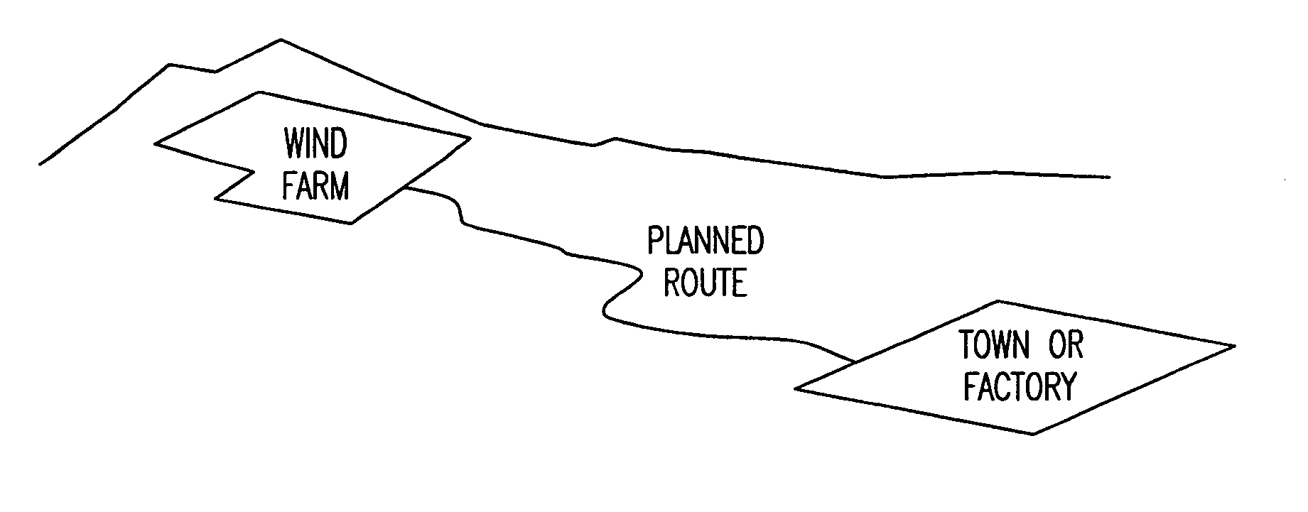
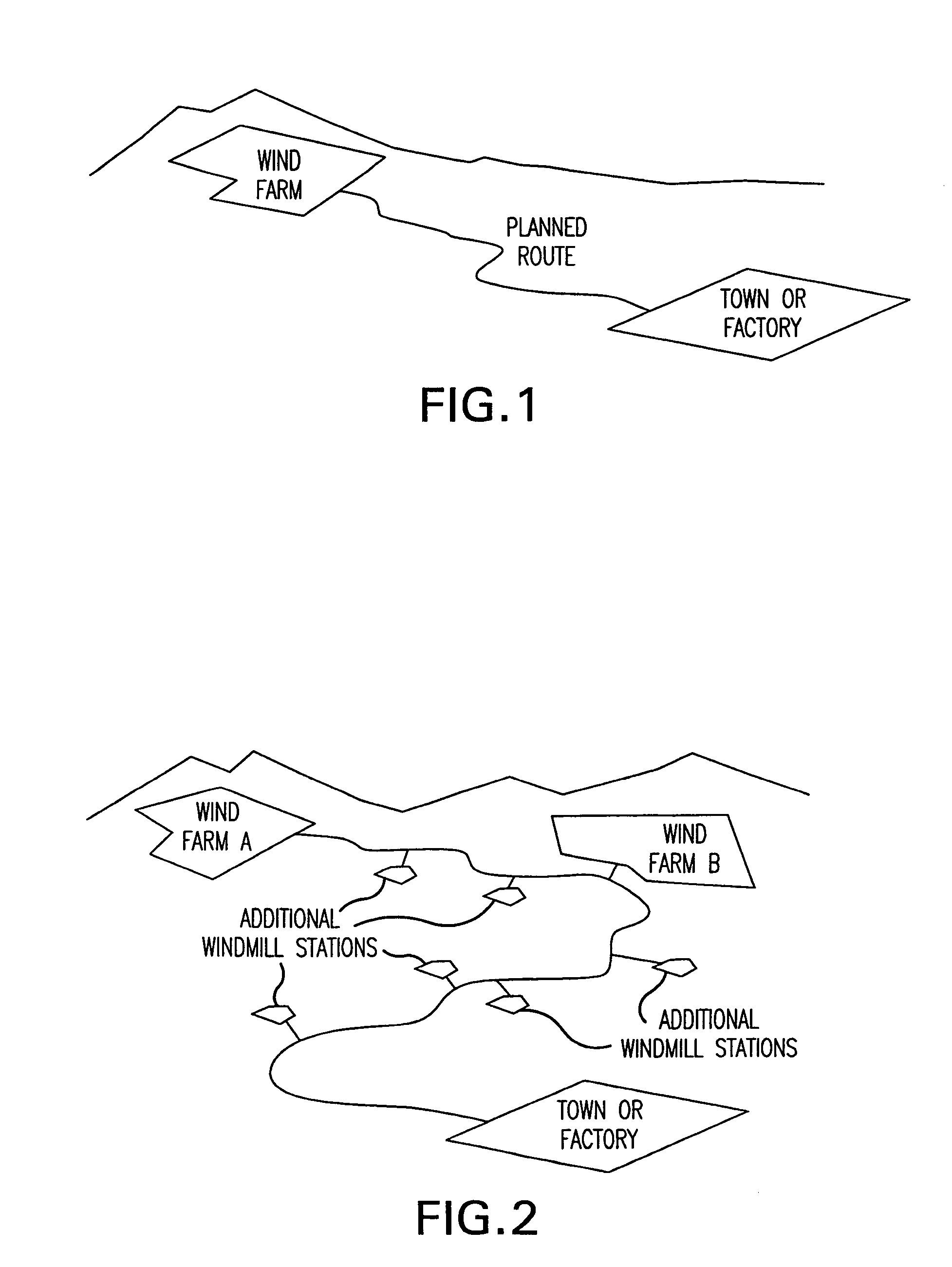
[0038] Another aspect of Applicant's invention takes into account the following: When determining the location of the wind farm, as well as where the pipeline is to be located, the method preferably takes into account existing roads, easements, underground pipes, railroad tracks, lines, cables, etc., and where they are located, so that the pipeline can be laid along the most economical and/or convenient path possible. That is, the pipeline is preferably located along a direct line or path extended along, or at least in close proximity to, existing roads, railroad tracks, easements, pipes, conduits, cables, etc., so that new roads, access, and open areas, etc., do

Problems solved by technology

In some remote areas of the country, however, electrical power is not always readily available, and efforts must be made to supply needed power to those areas.
For example, new electrical transmission lines, which are costly to install, may be required to enable facilities, and people who live and/or work in areas remote from the power grid, to receive access to electrical power.
Nevertheless, the cost of constructing electrical transmission lines, from the site to the nearest power grid, can be prohibitivel

Method used


Image

  • Method of transporting and storing wind generated energy using a pipeline
  • Method of transporting and storing wind generated energy using a pipeline
  • Method of transporting and storing wind generated energy using a pipeline

Examples


second embodiment

[0112] In a second embodiment, heating is preferably provided on a limited basis. For example, in this embodiment, only an existing heat source is preferably used, such as the waste heat generated by the compressors as the air is compressed, which can be stored in the pipeline. Additional heat from the sun, by locating the pipeline above ground, on the desert floor, can also be used. This way, there is a higher efficiency of delivery of electrical power, even though at the expense of less chilled air. In this embodiment, however, an effort is made to eliminate using any additional energy source to provide heat, which would require its own power source to operate.

first embodiment

[0113] This embodiment has the advantage of being able to generate, in addition to electrical power, a certain amount of chilled air. This embodiment preferably takes advantage of the chilled air being generated by the turbo expander, i.e., as the compressed air is released, to provide chilled air for cooling purposes. For example, the waste chilled air from the turbo expander can be used for refrigeration and air conditioning purposes, which is especially helpful when the community or facility that the pipeline services is located in a warm climate. When the waste heat is used, the system contemplates being able to heat the compressed air in the pipeline from normal ambient temperature of about 70 degrees F., as in the first embodiment, to a temperature of about 250 degrees F., wherein the chilled air that is co-generated can then be increased in temperature to about minus 75 degrees F.

3. The Third Configuration:

third embodiment

[0114] In a third embodiment, the system is advantageously provided with several heaters to enhance the generation of electricity from the compressed air. For example, waste heat from the compressors, or other heat sources, can be provided, as the compressed air is released, to maximize the generation of electricity thereby. For example, this embodiment contemplates using at least one of three different types of heating systems, including 1) solar thermal collectors that utilize energy from the sun, including locating the pipeline above ground, to make efficient use of the sun's heat, 2) waste heat collectors to circulate the waste heat generated by the compressor to the compressed air in the pipeline, and 3) a separate heating unit, such as a fossil fuel burner, to introduce heat into the pipeline, or add heat to the turbo expander input as compressed air is being released by the turbo expander. The invention also contemplates using other standard methods of providing heat to the c...


PUM


Abstract

The invention relates to a method of storing and transporting wind generated power in the form of compressed air energy, via a pipeline, from a location where wind conditions are ideal, to a facility or community where energy is needed. The method preferably comprises using at least one wind turbine to drive a compressor to compress air into storage, wherein the size and length of the pipeline can be adapted to reduce the pressure losses that are experienced along the length of the pipeline. The pipeline can be located on railroad ties, or on the desert floor, or can be extended along paths where existing right of ways are provided. The facility or community using the energy can use energy in the form of electricity, or to drive pneumatic tools or equipment, or to generate chilled air as a by-product, which can be used for refrigeration, air conditioning or desalination. A utility or grid can be provided to generate compressed air energy when the wind is not blowing, wherein compressed air energy can be produced and stored during low demand periods, and used during high demand periods.

Description

RELATED APPLICATIONS [0001] This application is a Continuation in Part of U.S. Ser. No. 11 / 407,733, filed Apr. 20, 2006, which claims priority from U.S. Ser. No. 10 / 857,009, filed Jun. 1, 2004, which claims priority from U.S. Ser. No. 60 / 474,551, filed on May 30, 2003. This application also claims priority from U.S. Ser. No. 60 / 834,232, filed on Jul. 28, 2006; U.S. Ser. No. 60 / 763,577, filed Jan. 31, 2006; and U.S. Ser. Nos. 11 / 242,378, filed Oct. 3, 2005, and 10 / 865,865, filed Jun. 14, 2004, which claim priority from U.S. Ser. No. 60 / 478,220, filed Jun. 13, 2003; and U.S. Ser. No. 11 / 134,801, filed May 20, 2005, which claims priority from U.S. Ser. No. 10 / 263,848, filed Oct. 4, 2002, which claims priority from U.S. Ser. Nos. 60 / 408,876, filed Sep. 9, 2002, and 60 / 327,012, filed Oct. 5, 2001. All of the above applications are incorporated herein by reference.FIELD OF THE INVENTION [0002] The present invention relates to a method of transporting and storing wind generated energy, and...

Claims


Application Information

Patent Timeline
IPC IPC(8): F03B13/00H02P9/04
CPCF03D9/028Y02E10/72Y02E60/15F05B2240/96F03D9/17F03D9/28F03D9/257Y02E60/16Y02E70/30Y02P90/50Y02A20/141
Inventor ENIS, BEN M.LIEBERMAN, PAUL
Owner ENIS BEN M
Why Eureka
Try Eureka