Power tool and method for assembling the same

a technology of power tools and power tools, applied in the field of power tools, can solve the problems of poor assembling operation efficiency and inability to remove the protection cap 142, and achieve the effects of reducing the number of parts, enhancing the assembling efficiency of the power tool, and reducing the cost of the power tool

Inactive Publication Date: 2007-08-09
KOKI HLDG CO LTD
View PDF15 Cites 18 Cited by
  • Summary
  • Abstract
  • Description
  • Claims
  • Application Information

AI Technical Summary

Benefits of technology

[0018] The invention aims at eliminating the above problems. Thus, it is an object of the invention to provide a power tool which can accomplish the positioning and rotation prevention of a yoke with high operation efficiency, and a method for assembling such power tool.
[0019] Also, it is another object of the invention to provide a power tool which can achieve the assembling of a direct-current motor into a cylindrical-shaped housing with high operation efficiency, and a method for assembling such power tool.

Problems solved by technology

However, when the assembling method using the protection cap 142 shown in FIG. 11 is applied to the cylindrical-shaped housing, since the yoke set 130 is previously incorporated in the barrel portion of the cylindrical-shaped housing, there arises a problem that, after the armature set 140 is inserted into the inside of the yoke set 130, the protection cap 142 cannot be removed.
Therefore, it is not easy to incorporate the yoke set 130 into the cylindrical-shaped housing, resulting in the poor efficiency of the assembling operation.

Method used


Image

  • Power tool and method for assembling the same
  • Power tool and method for assembling the same
  • Power tool and method for assembling the same

Examples


Embodiment Construction

[0053] Now, description will be given below of an embodiment according to the invention with reference to the accompanying drawings.

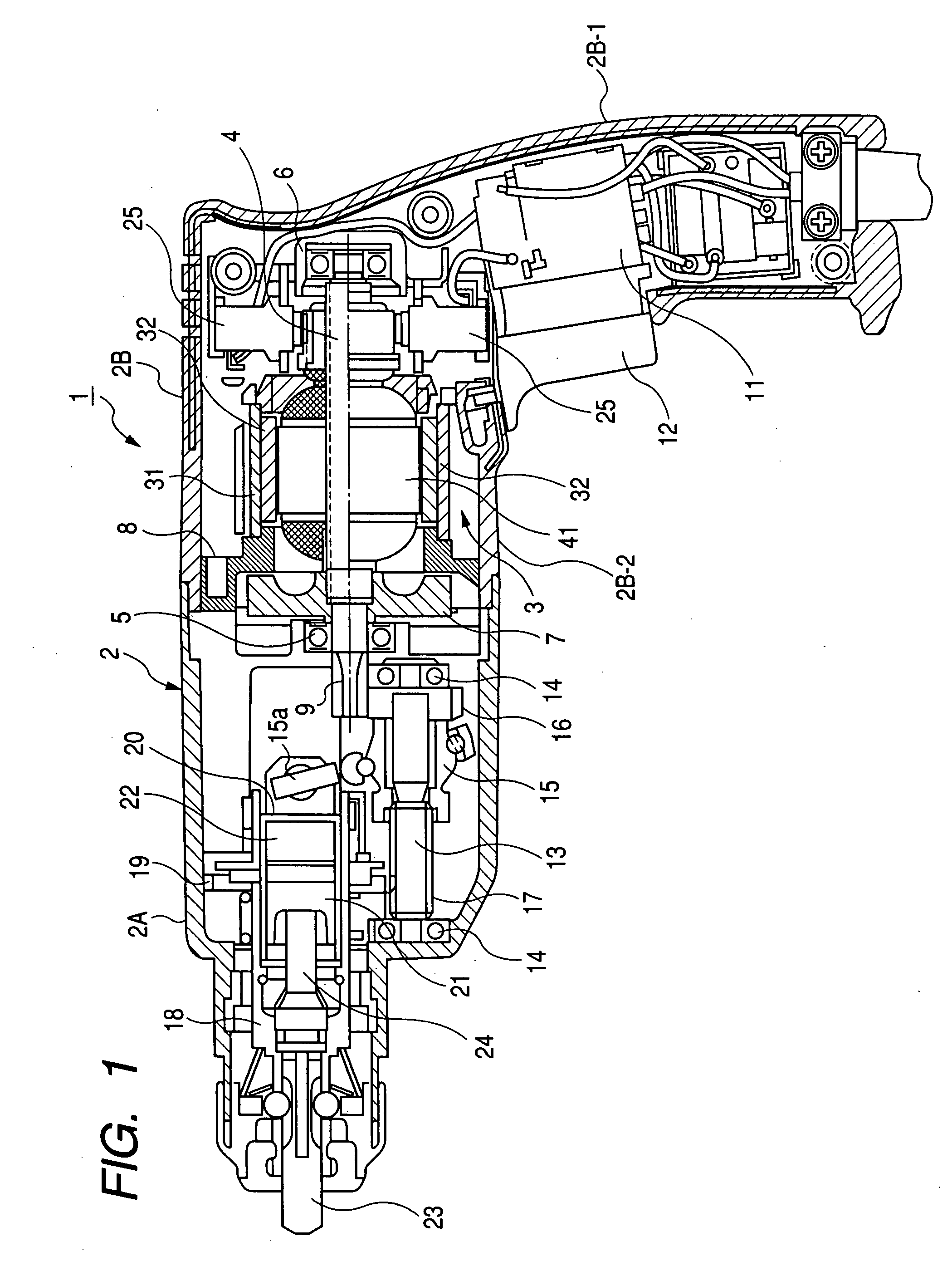
[0054] Firstly, description will be given below of the structure of a power tool according to the invention with reference to FIG. 1.

[0055]FIG. 1 is a longitudinal section view of a rotary hammer drill 1 as an embodiment of a power tool according to the invention. The rotary hammer drill 1 shown in FIG. 1 incorporates a direct-current motor 3 functioning as a drive source within a resin-made cylindrical-shaped housing 2 functioning as an outer frame member, while the rotation shaft (motor shaft) 4 of the direct-current motor 3 is rotatably supported at the two ends thereof by bearings 5 and 6. And, to the rotation shaft 4, there is secured a cooling fan 7 and, in the periphery of the cooling fan 7, there is disposed a fan guide 8 used to form an air passage. Further, on the front end portion of the rotation shaft 4 that projects forwardly from the bea...


PUM


Abstract

A power tool 1 includes a cylindrical-shaped yoke 31, magnets 32 provided in the interior of the yoke 31, an armature 41 disposed rotatably in the interior of the yoke 31, a cooling fan 7 rotatably secured to the armature 41, a fan guide 8 disposed on the periphery of the cooling fan 7, and a cylindrical-shaped housing 2 for storing the yoke 31 therein. The fan guide 8 is contacted with the axial-direction one end face of the yoke 31, and the fan guide 8 is engaged with the yoke 31 in the rotation direction thereof.

Description

BACKGROUND OF THE INVENTION [0001] 1. Field of the Invention [0002] The present invention relates to a power tool including a direct-current motor as its drive source such as a rotary hammer drill. [0003] 2. Description of Related Art [0004] A power tool using a direct-current motor as its drive source has been widely put to practical use. A direct-current motor, which is used as the drive source of a power tool of this type, as shown in FIG. 10, is composed of a yoke set 130 and an armature set 140. [0005] Here, the yoke set 130 is composed of a substantially cylindrical-shaped yoke 131 made of ferromagnetic material such as iron, two or more arc-curve-shaped magnets 132 disposed inside the yoke 131, and a ring-shaped dust guard 133 mounted on the yoke 131 in such a manner that it is fitted with the peripheral edge of the opening of the axial-direction one end portion of the yoke 131. [0006] Also, the armature set 140 is composed of a rotation shaft 104 the two end portions of whic...

Claims


Application Information

Patent Timeline
Patent Type & Authority Applications(United States)
IPC IPC(8): H01H51/22H02K7/14H02K9/06H02K23/04H02K1/06
CPCH02K5/148H02K5/15H02K5/1732B25F5/02H02K9/06H02K15/02H02K7/145
Inventor TAKAHASHI, SHIGERUTADOKORO, NAOKISAITO, TAKUMA
Owner KOKI HLDG CO LTD
Why Eureka
Try Eureka