Plasma display apparatus

a technology of display apparatus and plasma, which is applied in the direction of gas discharge vessel/container, incadescent envelope/vessel, gas discharge tube, etc., can solve the problems of reducing pdp manufactures are faced with cutting down the retail price of pdps, and the price of mesh type electromagnetic shield is usually very expensive compared, so as to achieve the effect of fully reducing all unnecessary radiation

Inactive Publication Date: 2007-08-09
HITACHI LTD
View PDF3 Cites 13 Cited by
  • Summary
  • Abstract
  • Description
  • Claims
  • Application Information

AI Technical Summary

Benefits of technology

[0012]In this manner, all unnecessary radia...

Problems solved by technology

Along with a severe decline in price of PDPs in recent years, a number of PDP manufactures are faced with cutting down their official retailing prices of PDPs.
Unfortunately however, the mesh type electromagnetic shield is usually very expensive compared with the transparent conductive film formed by sputtering because an etching process should be carried out for the formation of a metal mesh.
Despite the advantage of cost-effectiveness, the transpare...

Method used


Image

  • Plasma display apparatus
  • Plasma display apparatus
  • Plasma display apparatus

Examples


embodiment 1

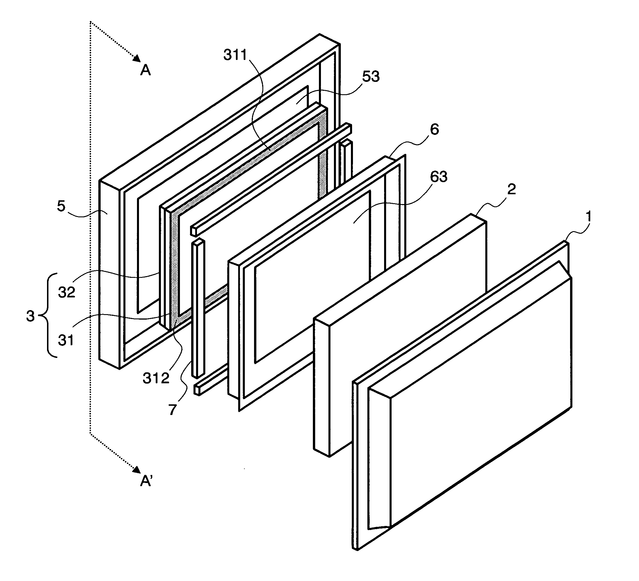
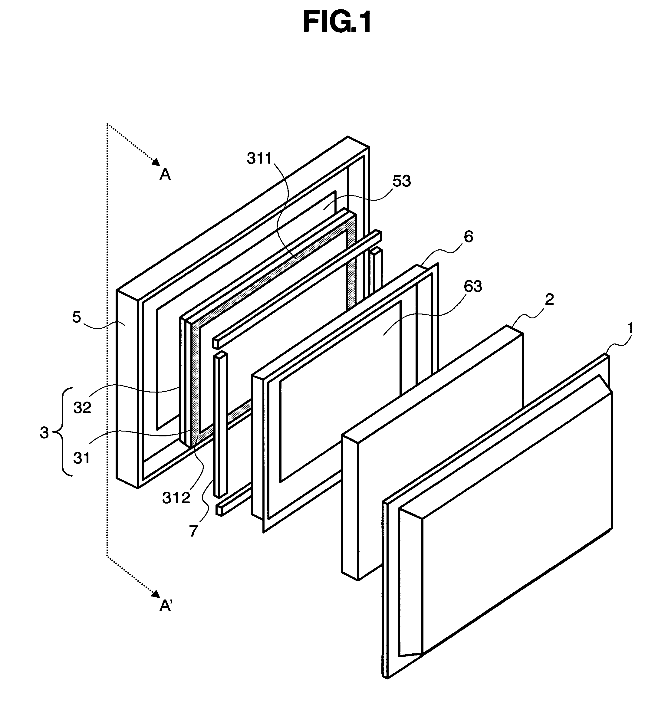
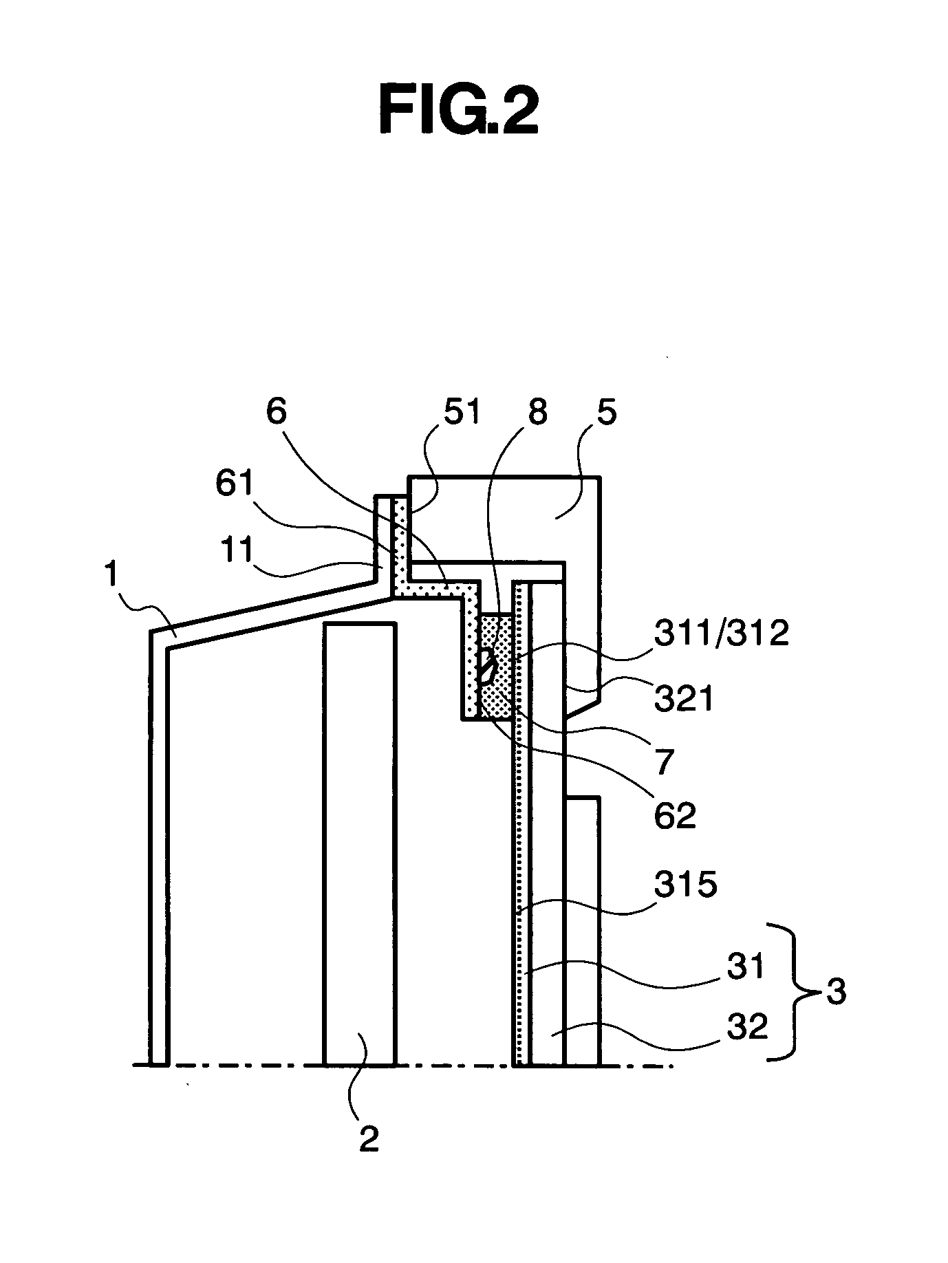
[0021]FIG. 1 is an exploded perspective view of main parts of a plasma display apparatus in accordance with the present invention, and FIG. 2 is a partial, cross sectional view of main parts of a plasma display apparatus according to a first embodiment of the present invention, taken along line A-A′ of FIG. 1. To be more specific, FIG. 2 only shows the upper part, while the lower part is omitted.

[0022]First, the constitution of a plasma display apparatus will be explained with reference to FIG. 1. As shown in FIG. 1, an optical filter 3 having a spherical shape almost similar to the PDP is disposed at the front surface side (viewer's side) of the PDP 2. The optical filter 3 is formed by interposing an adhesive layer (not shown) between an optical filter member 31 having an electromagnetic shield (not shown) capable of shielding electromagnetic waves and a glass substrate 32 made of transmitting materials.

[0023]Electromagnetic shields are largely divided into two types. One is a mesh...

embodiment 2

[0055]The optical filter employed in the embodiment 1 had the electrode of the electromagnetic shield on the surface of the PDP side, but it can also be installed at the front case side (viewer's side). FIG. 6 is a partial, cross sectional view showing main parts of a plasma display apparatus according to a second embodiment of the present invention, in which the electrode of the electromagnetic shield is installed at the front case side.

[0056]As shown in FIG. 6, a transparent conductive film type optical filter 3′ includes an electrode 312′ of an electromagnetic shield 315′ on the front case 5 side at an end portion 311′ of the periphery thereof. The rear surface side (PDP side) and front surface side of the optical filter 3′ include a first fixing member 9a and a second fixing member 9b for retaining / fixing the optical filter. Both the first fixing member 9a and the second fixing member 9b have openings (not shown) through which an image light emitted from the PDP passes. An end...


PUM


Abstract

Disclosed is an optical filter having an electromagnetic shield capable of shielding unnecessary radiation of electromagnetic waves from a PDP, in which satisfactory reduction of undesired radiation is achieved even by employing a relatively low price optical filter. A plasma display apparatus of the invention includes: a conductive rear surface cover covering a rear surface of a plasma display panel; an optical filter provided with an conductive layer having a surface resistance of 0.5 Ω/square or above, which is disposed at the front surface of the plasma display panel and serves to reduce leakage of electromagnetic waves from the plasma display panel; optical filter protecting members electrically connected with the rear surface cover, for protecting/retaining the optical filter; and a conductive body having elasticity, which is interposed between the optical filter and the optical filter protecting member. A plurality of bosses are formed in the optical filter protecting members. A part of the elastic conductive body is compressed by the bosses and connection resistance with the elastic conductive body is reduced.

Description

BACKGROUND OF THE INVENTION[0001]1. Field of the Invention[0002]The present invention relates in general to a display apparatus, more specifically, to a plasma display apparatus using a plasma display panel.[0003]2. Description of the Related Art[0004]A plasma display apparatus using a plasma display panel (hereinafter referred to as “PDP”) as a display apparatus employs an electromagnetic shield as a measure against electromagnetic interference (EMI) so that unnecessary electromagnetic waves (hereinafter referred to as “unnecessary radiation”) do not leak outside of the apparatus. An electromagnetic wave emitted from the front surface (display surface) of the PDP is shielded by a conductive layer (hereinafter referred to as “electromagnetic shield”) installed at a light-permeable optical filter on the front surface of the PDP. For the purpose of reducing unnecessary radiation, Japanese Patent Laid-Open Publication Nos. 2004-45778 and 2004-170624 disclosed a new scheme for attaching...

Claims


Application Information

Patent Timeline
IPC IPC(8): H01K1/30H01J5/16H01J61/40
CPCH01J11/44H05K9/0054H01J2211/446
Inventor KUBOTA, HIDENAOYAMADA, YUTAKA
Owner HITACHI LTD
Why Eureka
Try Eureka