Method for ultra-fast controlling of a magnetic cell and related devices

Inactive Publication Date: 2007-08-09
INTERUNIVERSITAIR MICRO ELECTRONICS CENT (IMEC VZW)
View PDF2 Cites 21 Cited by
  • Summary
  • Abstract
  • Description
  • Claims
  • Application Information

AI Technical Summary

Benefits of technology

[0039] It is an advantage of embodiments of the present invention that no external magnetisation input such as an externally induced magnetic field or an incident magnetic wave is needed for operating the device.
[0040] It is an advantage of embodiments of the present invention that the systems allows to influence the magnetisation of the magnetic elements. Features described in specific embodiments are not limited to these specific embodiments and may be mutatis mutandis be applied, used or introduced in

Problems solved by technology

All the above described techniques, however, have several different problems, such as e.g. current lines are needed for both biasing and magnetic assessment, a bit selection scheme has stringent timing requirements, power consumption is relatively high and different metallisation levels are required.
Furthermore, reference cells can be necessary for comparing states during read-out, which reduces the effective cell density.
Operating at ferrom

Method used


Image

  • Method for ultra-fast controlling of a magnetic cell and related devices
  • Method for ultra-fast controlling of a magnetic cell and related devices
  • Method for ultra-fast controlling of a magnetic cell and related devices

Examples


Example

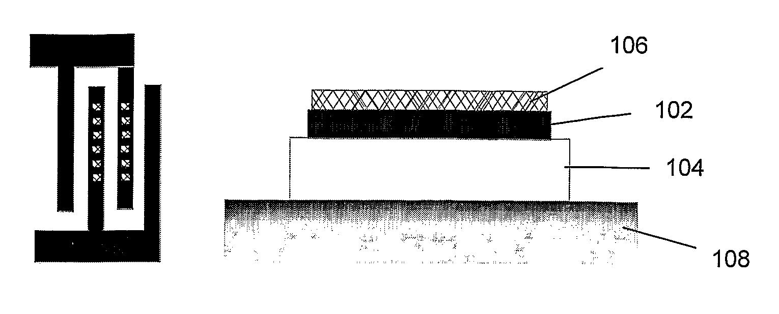
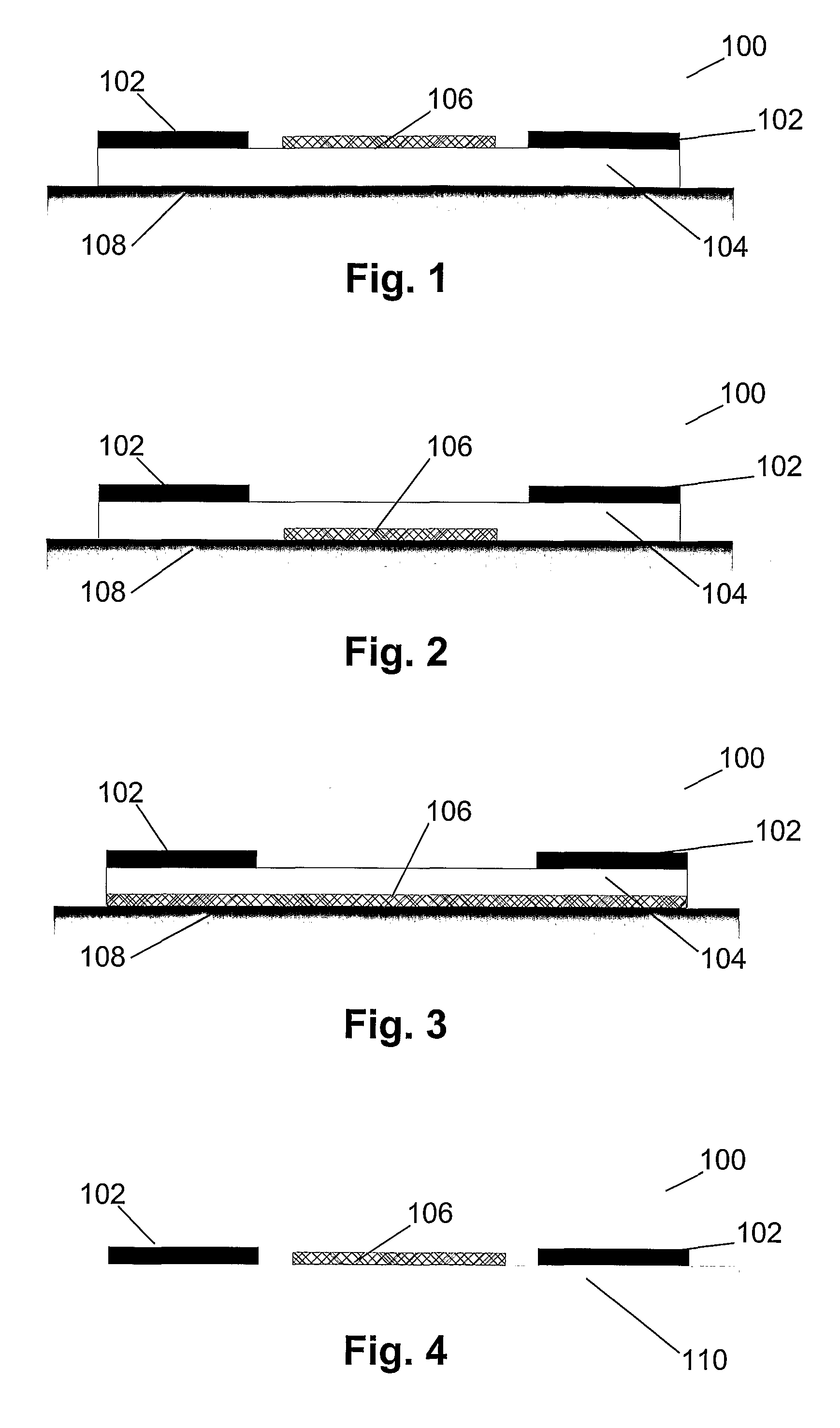
[0074] In a first embodiment a device 100 for switching and / or determining and / or manipulating and / or changing a magnetisation state of a ferromagnetic component is described. The device 100 comprises a surface acoustic wave (SAW) generating means 102, a transport layer 104 to allow propagation of the generated SAW and in which a SAW has the form of a stress and / or strain wave, and a magnetic element 106, also called magnetic cell or cell, whose state can be switched or determined or assessed using the stress and / or strain wave. Strictly spoken, the transport layer 104 is also part of the SAW generating means 102. Surface acoustic waves are generated by the SAW generating means 102 and need a material for their transfer, which is the transport layer 104. Therefore, the SAW generating means 102 and the transport layer 104 belong together. However, for the ease of explanation, in the further description, the SAW generating means 102 and the transport layer 1041 will be discussed separ...

Example

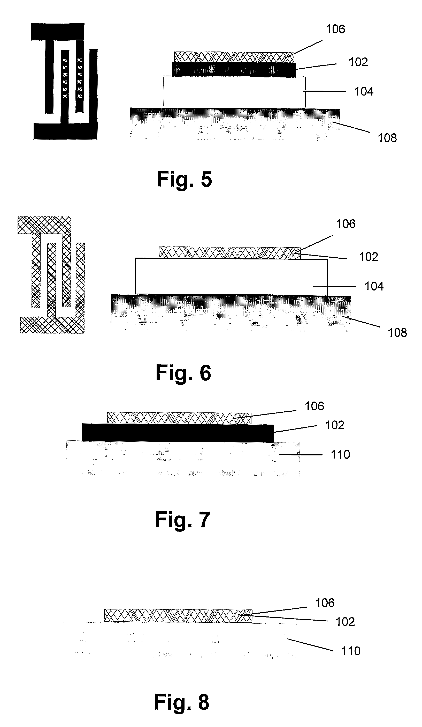
[0084] In a second embodiment, the invention relates to a device 100 for switching and / or determining and / or manipulating and / or changing a magnetisation state of a ferromagnetic component, comprising the same components and functionalities as described in the first embodiment, but wherein the magnetic element 106 is in direct contact with the SAW generating means 102, such as e.g. the IDT or wherein the IDT is itself the magnetic element 106 of interest. The magnetic element 106 in direct contact with the SAW generating means 102 may e.g. be deposited directly on top of the SAW generating means 102. Such configurations are depicted in FIG. 5 to FIG. 8. FIG. 5 indicates the configuration wherein a magnetic element 106 is deposited on top of a SAW generating means 102 whereas FIG. 6 indicates the configuration wherein the magnetic element 106 of interest is the SAW generating means 102 itself. In both configurations a transport layer 104 and a substrate 108 is present. FIG. 7 and FIG...

Example

[0086] In a third embodiment, a device 100 according to, i.e. having the same components as, any of the configurations described in the previous embodiments is provided, whereby the SAW generating means 102 can apply a shear SAW. A shear SAW, as depicted in FIG. 11a, is a surface acoustic wave that is launched by a SAW generating means 102, e.g. an IDT, and that makes the surface deform in a sinusoidal manner in plane (X-Y plane), generating a shear strain on every spot where the SAW passes. The magnitude of the shear strain, at given time and place, is depending on several parameters, from which the most important are the voltage applied on the SAW generating means 102 and the phase of the wave. So, a layer deposited in the path of the SAW, at its fixed location, senses a shear strain which changes in magnitude over time.

[0087] If this layer is a ferromagnetic layer, then the shear strain generates an effective magnetic field in the layer, as shown in FIG. 11b. As the magnetic ele...


PUM


Abstract

The present invention relates to a device and corresponding method for ultrafast controlling of the magnetization of a magnetic element. A device (100) includes a surface acoustic wave generating means (102), a transport layer (104), which is typically functionally and partially structurally comprised in said SAW generating means (102), and at least one ferromagnetic element (106). A surface acoustic wave is generated and propagates in a transport layer (104) which typically consists of a piezo-electric material. Thus, strain is induced in the transport layer (104) and in the ferromagnetic element (106) in contact with this transport layer (104). Due to magneto elastic coupling this generates an effective magnetic field in the ferromagnetic element (106). If the surface acoustic wave has a frequency substantially close to the ferromagnetic resonance (FMR) frequency νFMR the ferromagnetic element (106) is absorbed well and the magnetisation state of the element can be controlled with this FMR frequency. The device can be used in an RF-magnetic resonator, a sensor and a camera. The corresponding method can be used for ultrafast reading-out and switching of magnetic components and in magnetic logic.

Description

TECHNICAL FIELD OF THE INVENTION [0001] The present invention relates to the field of magnetics. The invention relates to methods, techniques and corresponding devices for controlled manipulation of magnetisation states of ferromagnetic entities as e.g. magnetic layers, cells and components. The invention also relates to RF resonators and magnetic logic and magnetic memories. BACKGROUND OF THE INVENTION [0002] Currently, magnetisation states in a ferromagnetic component, as e.g. a ferromagnetic MRAM cell, are being manipulated, e.g. switched or changed, and assessed, e.g. read or written, by magnetic fields generated by neighbouring electrical currents, or by applying external magnetic fields. [0003] The technique of magnetic field induced switching by current conductors is widespread and is currently used in a wide series of commercial products. Several types of magnetic field induced switching by current conductors are known. The switching is generally done by a static method, whe...

Claims


Application Information

Patent Timeline
IPC IPC(8): G11C11/15G01R33/02G10K11/36G11C11/14G11C11/16H01F10/193H01F10/26H01F10/32H01L41/00H01L43/08H03B5/40H03B9/14H03H2/00H03H9/02H03H9/135H03H9/42H03H9/64H03K19/16H03K19/19
CPCB82Y25/00H03B15/006G11C11/14G11C11/15H01F10/193H01F10/26H01F10/3213H01F10/3254H01F10/3268H01L43/08H03H2/001H03H9/02574H03H9/02645H03H9/02976H03H9/135H03H9/6486H03K19/19G01R33/02G11C11/161G11C11/1673G11C11/1675H10N50/10
Inventor EYCKMANS, WOUTERLAGAE, LIESBET
Owner INTERUNIVERSITAIR MICRO ELECTRONICS CENT (IMEC VZW)
Why Eureka
Try Eureka