Technique for determining whether to reestablish fast rerouted primary tunnels based on backup tunnel path quality feedback

a backup tunnel and primary tunnel technology, applied in the field of computer networks, can solve the problems of rerouting traffic, reducing the efficiency of backup tunnels, and burdensome management of interconnected computer networks

Active Publication Date: 2007-08-09
CISCO TECH INC
View PDF28 Cites 124 Cited by
  • Summary
  • Abstract
  • Description
  • Claims
  • Application Information

AI Technical Summary

Benefits of technology

[0025] Advantageously, the novel technique dynamically determines whether to reestablish a Fast Rerouted primary tunnel based on path quality feedback of a utilized backup tunnel in a computer network. By providing the head-end node of the primary tunnel with path quality feedback of the backup tunnel, the novel technique avoids reestablishing a potentially large number of tunnels over one or more alternate paths after a failure (and Fast Reroute) if the backup tunnels ha

Problems solved by technology

Since management of interconnected computer networks can prove burdensome, smaller groups of computer networks may be maintained as routing domains or autonomous systems.
Occasionally, a network element (e.g., a node or link) will fail, causing redirection of the traffic that originally traversed the failed network element to other network elements that bypass the failure.
Reconfiguring a network in response to a network element failure using, e.g., pure IP rerouting, can be time consuming.
While this approach provides maximum protection, it also requires a non-negligible amount of network resources (e.g., capacity/bandwidth) and may increase operational complexity.
This “best effort” approach does not guarantee that the path followed by the backup tunnel will have enough bandwidth to support the diverted primary tunnel at the time of failure without QoS degradation, however in many situations the path qua

Method used


Image

  • Technique for determining whether to reestablish fast rerouted primary tunnels based on backup tunnel path quality feedback
  • Technique for determining whether to reestablish fast rerouted primary tunnels based on backup tunnel path quality feedback
  • Technique for determining whether to reestablish fast rerouted primary tunnels based on backup tunnel path quality feedback

Examples


Embodiment Construction

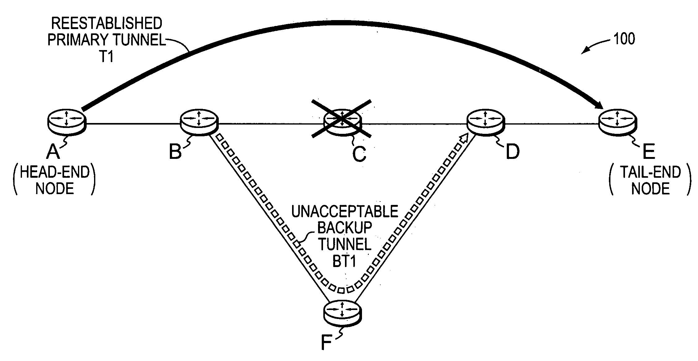
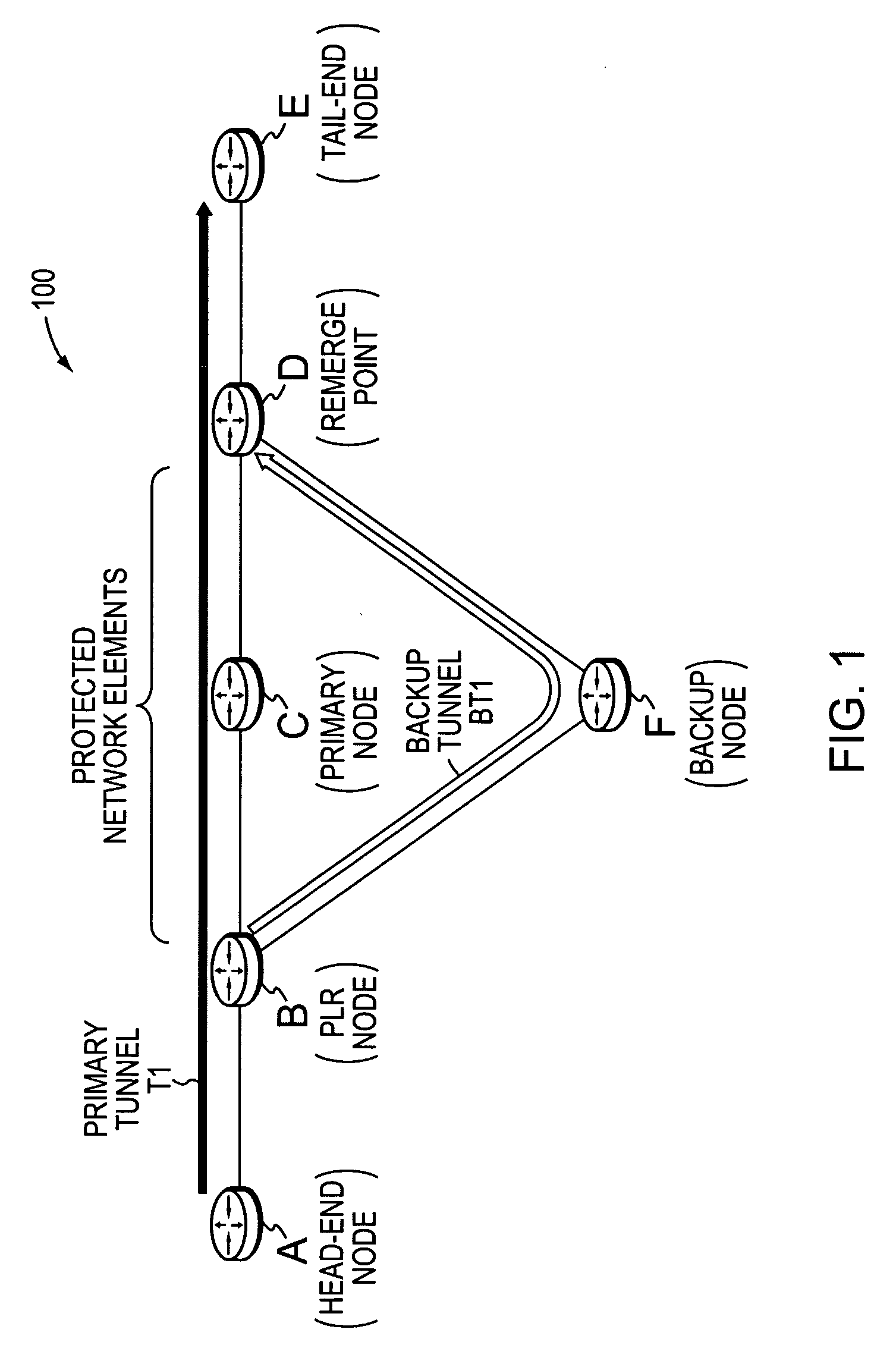
[0034]FIG. 1 is a schematic block diagram of an exemplary computer network 100 comprising a plurality of nodes A-F, such as routers or other network devices, interconnected as shown. The nodes may be a part of one or more autonomous systems, routing domains, or other networks or subnetworks. For instance, routers A and E may be provider edge (PE) devices of a provider network, (e.g., a service provider network) that are interconnected to one or more customer networks through customer edge (CE) devices (not shown, while the remaining nodes B-D and F may be core provider (P) devices, as will be understood by those skilled in the art. Those skilled in the art will also understand that the nodes A-F may be any nodes within any arrangement of computer networks, and that the view shown herein is merely an example. For example, the nodes may be configured as connections to / from one or more virtual private networks (VPNs), as will be understood by those skilled in the art. These examples ar...


PUM


Abstract

A technique dynamically determines whether to reestablish a Fast Rerouted primary tunnel based on path quality feedback of a utilized backup tunnel in a computer network. According to the novel technique, a head-end node establishes a primary tunnel to a destination, and a point of local repair (PLR) node along the primary tunnel establishes a backup tunnel around one or more protected network elements of the primary tunnel, e.g., for Fast Reroute protection. Once one of the protected network elements fail, the PLR node “Fast Reroutes,” i.e., diverts, the traffic received on the primary tunnel onto the backup tunnel, and sends notification of backup tunnel path quality (e.g., with one or more metrics) to the head-end node. The head-end node then analyzes the path quality metrics of the backup tunnel to determine whether to utilize the backup tunnel or reestablish a new primary tunnel.

Description

BACKGROUND OF THE INVENTION [0001] 1. Field of the Invention [0002] The present invention relates to computer networks and more particularly to dynamically determining whether to reestablish a Fast Rerouted primary tunnel based on path quality feedback of a utilized backup tunnel in a computer network. [0003] 2. Background Information [0004] A computer network is a geographically distributed collection of nodes interconnected by communication links and segments for transporting data between end nodes, such as personal computers and workstations. Many types of networks are available, with the types ranging from local area networks (LANs) to wide area networks (WANs). LANs typically connect the nodes over dedicated private communications links located in the same general physical location, such as a building or campus. WANs, on the other hand, typically connect geographically dispersed nodes over long-distance communications links, such as common carrier telephone lines, optical light...

Claims


Application Information

Patent Timeline
IPC IPC(8): H04J3/14H04L45/24H04L45/28H04L45/50
CPCH04J3/14H04L12/4633H04L45/60H04L45/28H04L45/50H04L45/22
Inventor VASSEUR, JEAN-PHILIPPELO, ALTONCHARNY, ANNA
Owner CISCO TECH INC
Why Eureka
Try Eureka