
Control apparatus and control method for fuel cell

a fuel cell and control apparatus technology, applied in the direction of fuel cells, electrical apparatus, electrochemical generators, etc., can solve the problems of affecting the generation of electricity, and freezing under low temperature, so as to increase the generated electricity generation

Active Publication Date: 2007-08-09
TOYOTA JIDOSHA KK
View PDF9 Cites 10 Cited by
  • Summary
  • Abstract
  • Description
  • Claims
  • Application Information

AI Technical Summary

Benefits of technology

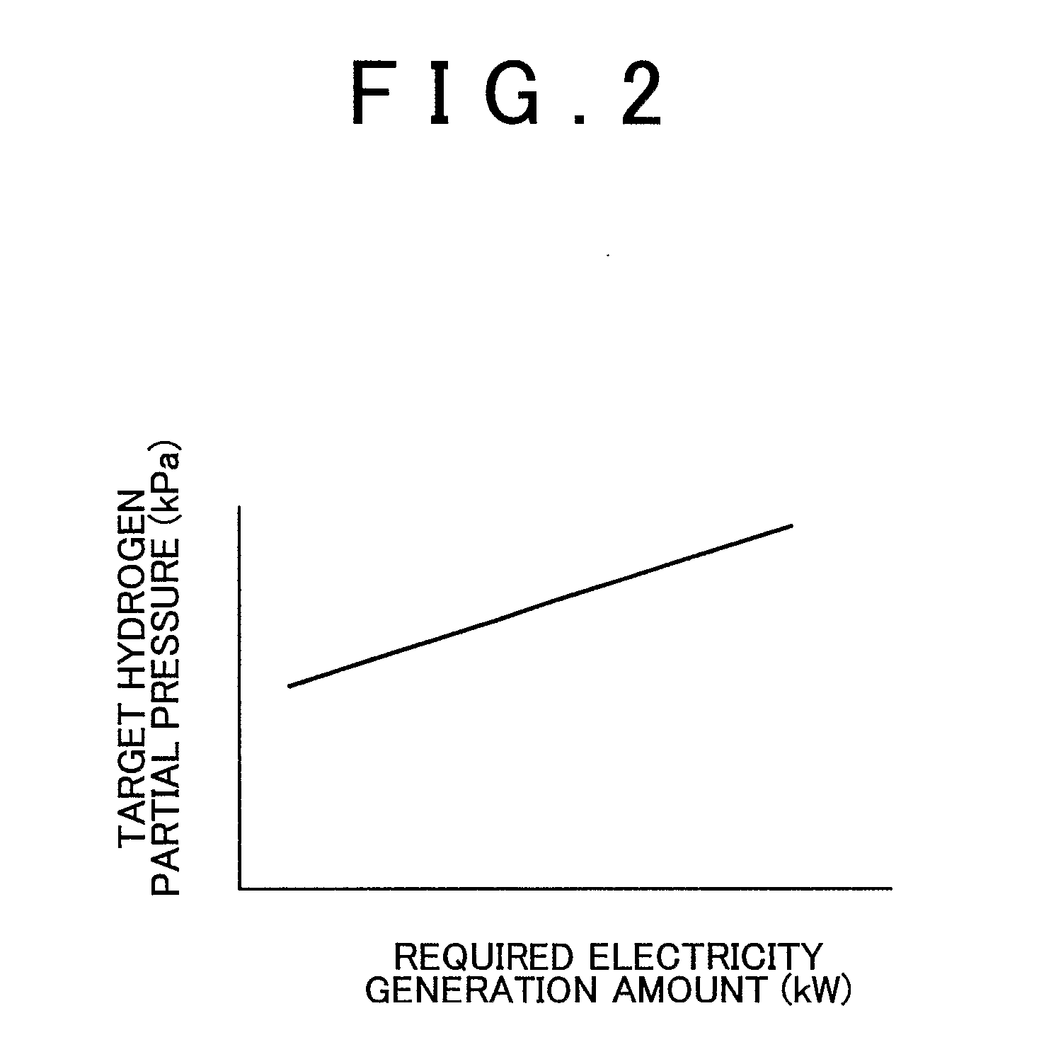
The invention provides a control apparatus and method for a fuel cell that increases the amount of generated electricity without being affected by the opening and closing of the exhaust valve on the hydrogen electrode side. This is achieved by detecting gas pressure in the oxidizing gas supply line and the cathode, and calculating the hydrogen supply pressure based on the detected gas pressure and the target hydrogen partial pressure. By controlling the hydrogen supply pressure, the fuel cell can generate more electricity without using the exhaust valve. Additionally, the control method takes into account the fuel cell temperature and adjusts the target hydrogen partial pressure accordingly to achieve the desired electricity generation amount.

Problems solved by technology

An increase in the concentration of impurities other than hydrogen on the hydrogen electrode side impedes an increase in hydrogen concentration, which in turn impedes an increase in the amount of electricity generated.
However, the exhaust valve of a fuel cell system (where impurities are discharged to increase the hydrogen concentration by opening and closing the exhaust valve during activation) may freeze under a low temperature.
Since time is required to defrost the frozen exhaust valve, the fuel cell cannot be activated in a short period of time.
Furthermore, fuel efficiency is not always satisfactory in a fuel cell system where the exhaust valve is opened and closed during operation to maintain the generated electricity amount, because hydrogen may be discharged along with impurities.

Method used


Image

  • Control apparatus and control method for fuel cell
  • Control apparatus and control method for fuel cell
  • Control apparatus and control method for fuel cell

Examples


Embodiment Construction

[0050] In the following description and the accompanying drawings, the present invention will be described in more detail in terms of exemplary embodiments.

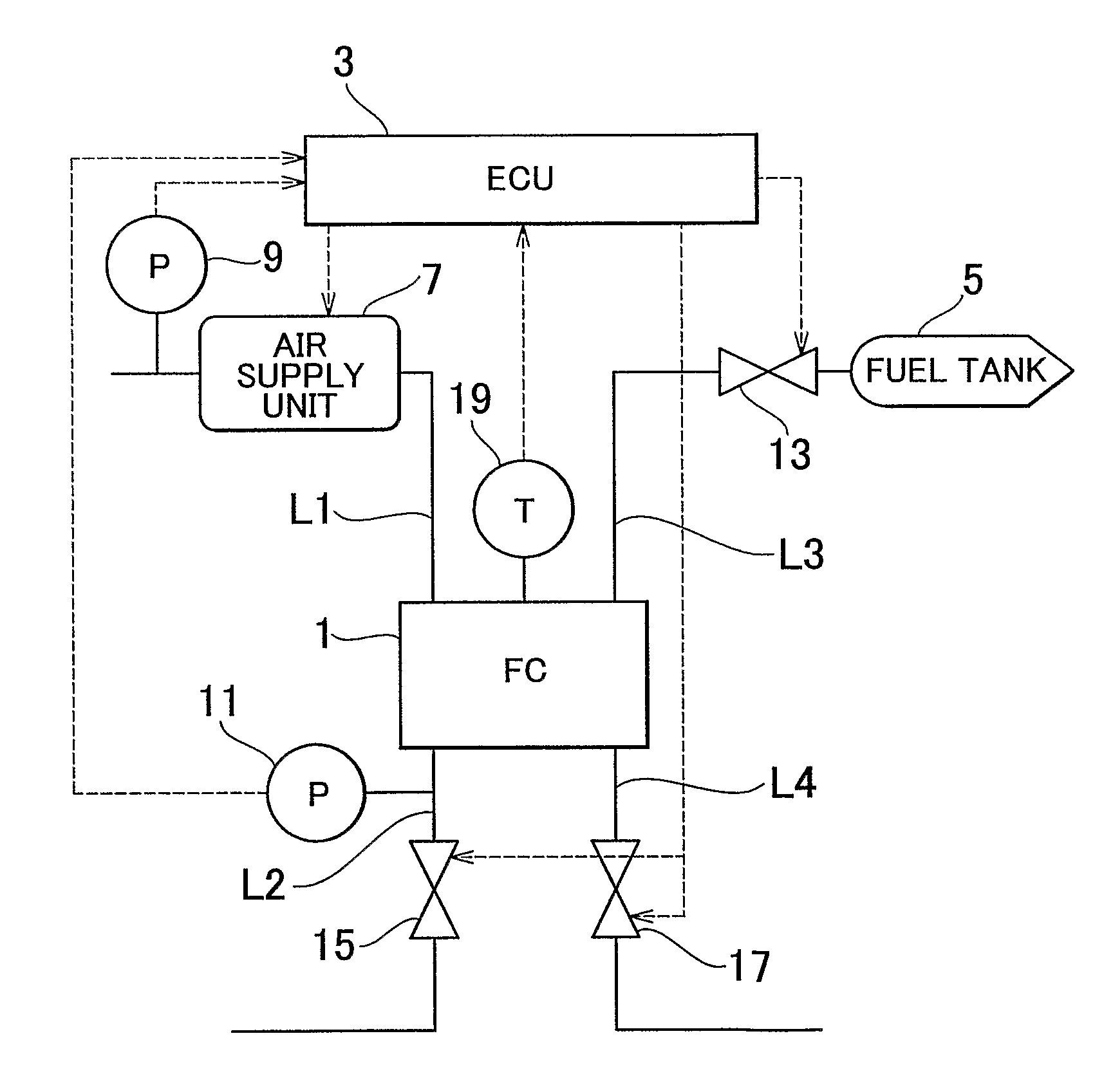
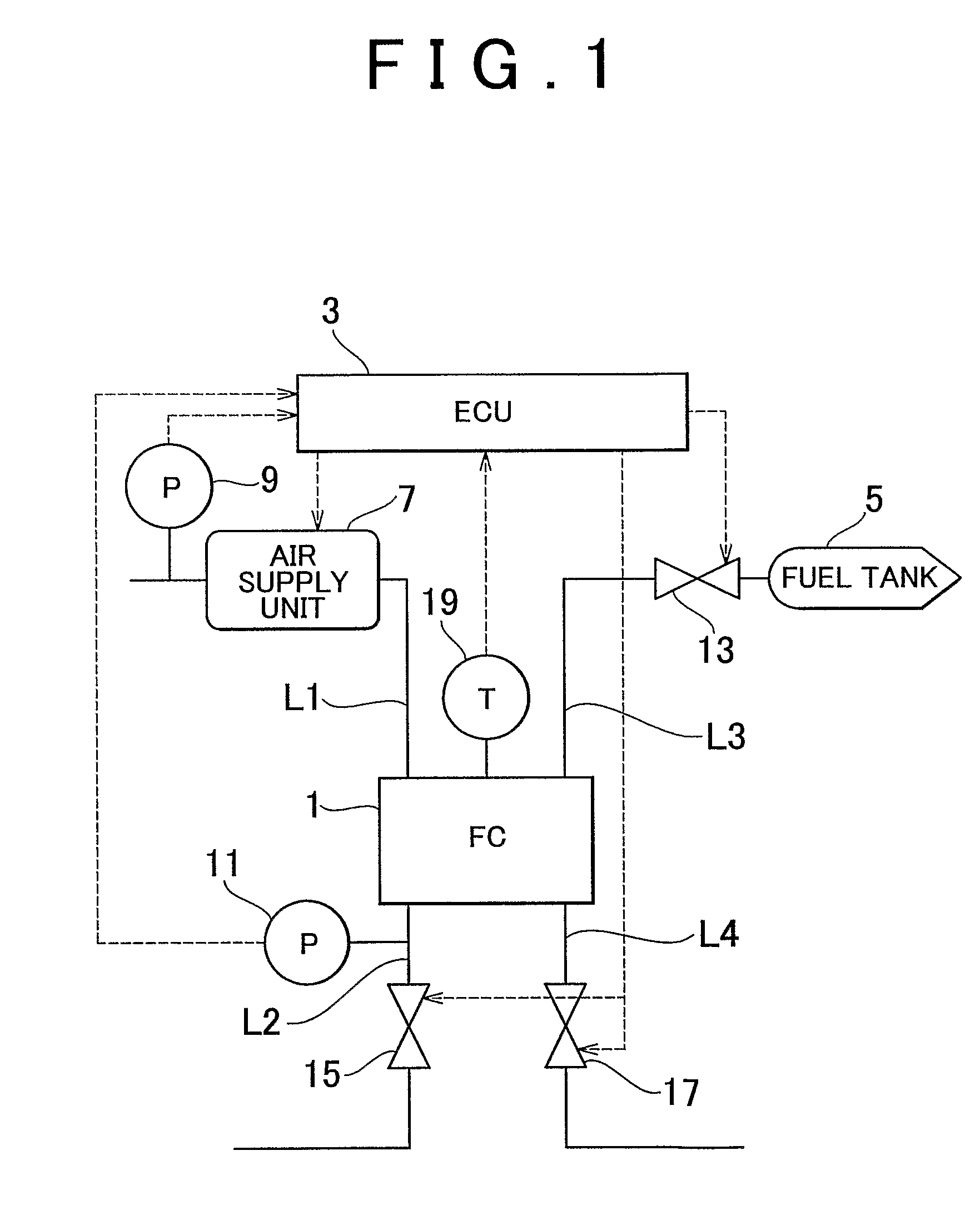
[0051]FIG. 1 is a schematic diagram of a fuel cell according to an embodiment of the invention. The fuel cell includes the following: a fuel cell body 1; an air supply unit 7 for supplying air acting as an oxidizing gas to an air electrode (also called a cathode) of the fuel cell body 1; an atmospheric pressure sensor 9 disposed in an air induction passage upstream of the air supply unit 7; an air electrode pressure sensor 11 for measuring gas pressure on the air electrode side; a regulating valve 15 for regulating gas pressure on the air electrode side; a fuel tank 5 for supplying hydrogen acting as a fuel gas to a hydrogen electrode (also called an anode) of the fuel cell body 1; a hydrogen supply valve 13 for controlling a supply pressure of hydrogen from the fuel tank 5; an exhaust valve 17 for controlling a discharge of fue...


PUM

PropertyMeasurementUnit
pressureaaaaaaaaaa
gas pressureaaaaaaaaaa
pressureaaaaaaaaaa

Abstract

A control apparatus for a fuel cell, including oxidizing gas supplying means for supplying oxidizing gas to a cathode via an oxidizing gas supply line; cathode-side gas pressure detecting means for detecting a gas pressure within the oxidizing gas supply line or the cathode; hydrogen supplying means for supplying hydrogen to an anode via a hydrogen supply line; target hydrogen partial pressure determining means for determining a hydrogen pressure among a gas pressure within the hydrogen supply line or the anode; hydrogen supply pressure calculating means for calculating a hydrogen supply pressure of hydrogen to be supplied to the fuel cell, based upon the target hydrogen partial pressure and the gas pressure detected by the cathode-side gas pressure detecting means; and hydrogen supply control means for supplying hydrogen from the hydrogen supplying means to the fuel cell at the hydrogen supply pressure, and the method thereof.

Description

BACKGROUND OF THE INVENTION [0001] 1. Field of the Invention [0002] The invention relates to a control apparatus and control method for a fuel cell. [0003] 2. Description of the Related Art [0004] A polymer electrolyte fuel cell has an electrolyte membrane, two catalyst layers formed by sandwiching the electrolyte membrane therebetween, and a pair of diffusion layers formed on outer sides of the two catalyst layers. One diffusion layer in the fuel cell is supplied with a fuel gas including hydrogen, and the other diffusion layer is supplied with an oxidizing gas including oxygen. The diffusion layer to which the fuel gas is supplied is called a hydrogen electrode, or an anode; the diffusion layer to which the oxidized gas is supplied is called an air electrode, or a cathode. [0005] Hydrogen supplied to the hydrogen electrode diffuses to the catalyst layer, and separates protons and electrons in the catalyst layer. Separated protons then pass through the electrolyte membrane along wi...

Claims


Application Information

Patent Timeline
Patent Type & Authority Applications(United States)
IPC IPC(8): H01M8/04H01M
CPCH01M8/04007H01M8/04104H01M8/0432H01M8/04395Y02E60/50H01M8/04462H01M8/04753H01M8/04761H01M8/04447
Inventor KATANO, KOJI
Owner TOYOTA JIDOSHA KK
Learn More