Battery module

a battery module and battery technology, applied in the field of batteries, can solve the problems of reducing the mechanical strength of the sheathing member b>14/b>, affecting the assembly process reducing the production efficiency of the battery module, so as to prevent the occurrence of short circuit and simplify the process of manufacturing the battery modul

Active Publication Date: 2007-08-09
LG ENERGY SOLUTION LTD
View PDF10 Cites 41 Cited by
  • Summary
  • Abstract
  • Description
  • Claims
  • Application Information

AI Technical Summary

Benefits of technology

[0017]In this structure, the upper-end frame or the lower-end frame may be provided with a terminal (detection terminal) for detecting the voltage and / or the temperature of the battery cells, and the upper-end frame may be provided with connection terminals for connecting the detection terminal to an external circuit. Consequently, when the battery cells are mounted to the frame member, the battery cells are automatically connected to the detecting means for detecting the voltage and / or the temperature of the battery cells, and therefore, a process for manufacturing the battery module is further simplified.
[0018]Especially, in a structure in which the detection terminal is mounted at the lower-end frame, and the detection terminal is connected to the connection terminals of the upper-end frame via a wire mounted in the side frame, the wire for connecting the detection terminal is not exposed to the outside. Consequently, the occurrence of short circuits is prevented during the assembly and the use of the battery module. The connection terminals may be constructed in a protruding structure or in a depressed structure.

Problems solved by technology

However, the mechanical strength of the sheathing member 14 is low.
Also, a device or a vehicle, in which a medium- or large-sized battery module is installed, has a limited installation space.
However, the attachment or the connection of the detecting means complicates the assembly process of the battery module.
In addition, short circuits may occur due to the provision of a plurality of wires.

Method used


Image

  • Battery module
  • Battery module
  • Battery module

Examples


Embodiment Construction

[0045]Now, preferred embodiments of the present invention will be described in detail with reference to the accompanying drawings. It should be noted, however, that the scope of the present invention is not limited by the illustrated embodiments.

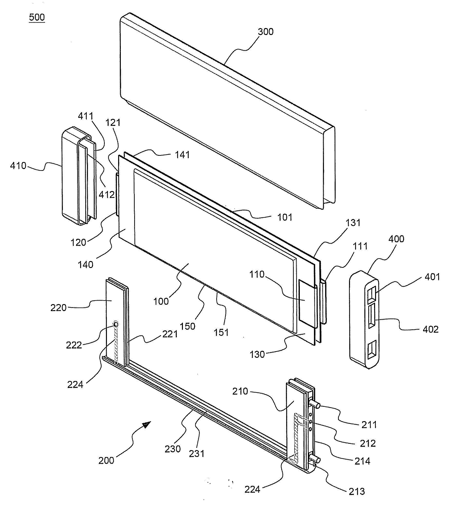
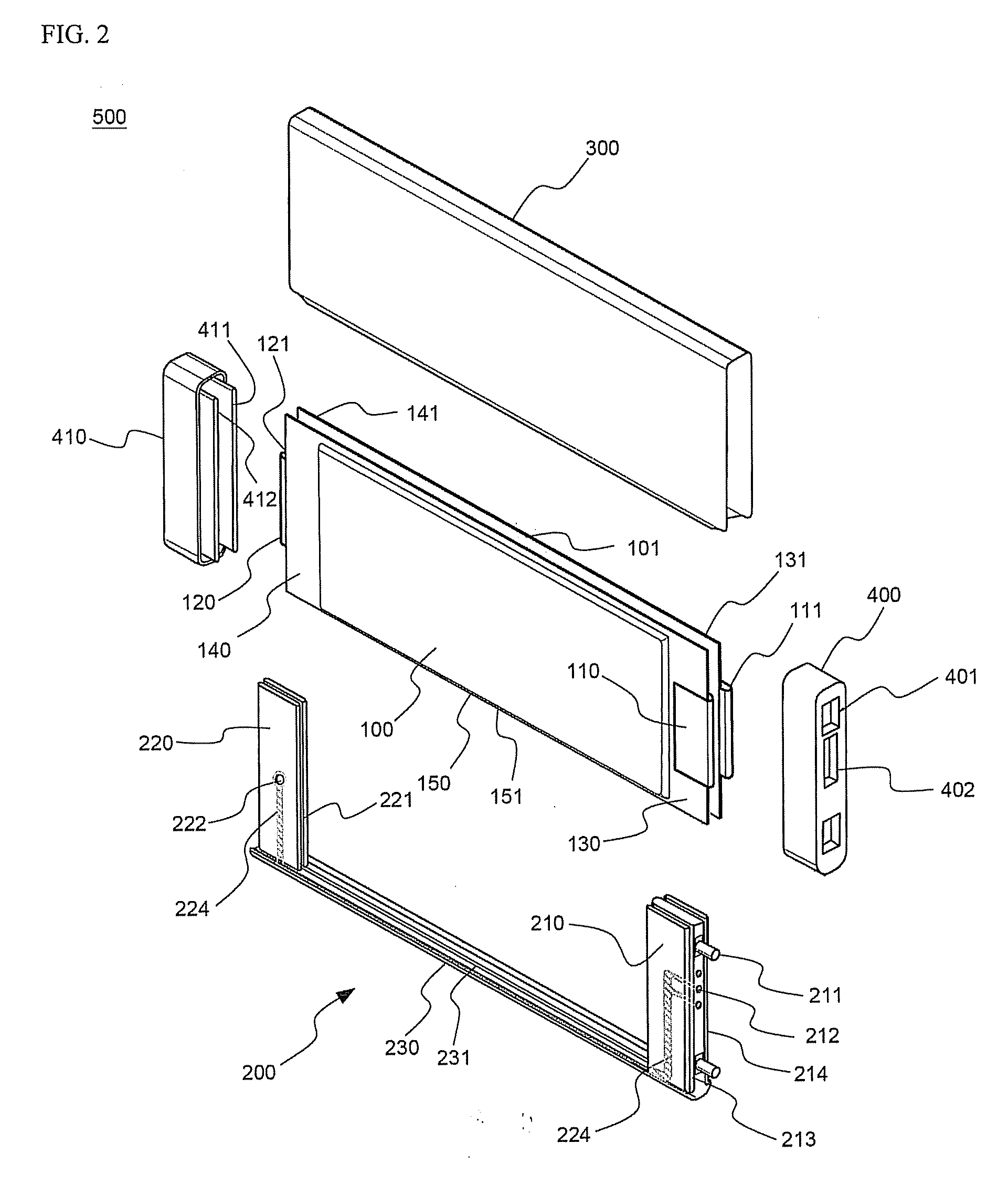
[0046]Hereinafter, the assembly process of a battery module according to a preferred embodiment of the present invention will be described with reference to FIG. 2, which is an exploded perspective view of the battery module.

[0047]Referring to FIG. 2, the battery module 500 includes a pair of battery cells 100 and 101, a frame member 200, a metal sheathing member 300, an upper-end cap 400, and a lower-end cap 410. The two battery cells 100 and 101 are mounted to the frame member 200 such that upper-end sealing parts 130 and 131, lower-end sealing parts 140 and 141, and right-side sealing parts 150 and 151 of the battery cells 100 and 101 are located at an upper-end frame 210, a lower-end frame 220, and a side frame 230 of the frame member 20...


PUM

PropertyMeasurementUnit
thicknessaaaaaaaaaa
voltageaaaaaaaaaa
temperatureaaaaaaaaaa

Abstract

Disclosed herein is a battery module including two battery cells, each of which has electrode terminals formed at upper and lower ends thereof. The battery module further includes a frame member, to which upper-end sealing parts, lower-end sealing parts, and one-side sealing parts of the battery cells are mounted, a metal sheathing member for covering the outer surfaces of the battery cells while the battery cells are mounted to the frame member, and caps (an upper-end cap and a lower-end cap) mounted to the upper and lower ends of the battery cells, respectively, which are covered by the metal sheathing member. According to the present invention, it is possible to minimize the weight and the size of the battery module while increasing the strength of the battery cells. Also, it is possible to easily mount the detecting means that detects the operation of the battery cells, and it is possible to effectively prevent the occurrence of short circuits during the assembly or the operation of the battery module. Furthermore, it is possible to easily perform the electric connection between the battery modules when manufacturing the medium- or large-sized battery module using the respective battery modules as unit bodies.

Description

FIELD OF THE INVENTION[0001]The present invention relates to a battery module, and, more particularly, to a battery module including two battery cells, each of which has electrode terminals formed at upper and lower ends thereof, wherein the battery module further includes a frame member, to which upper-end sealing parts, lower-end sealing parts, and one-side sealing parts of the battery cells are mounted, a metal sheathing member for covering the outer surfaces of the battery cells while the battery cells are mounted to the frame member, and caps (an upper-end cap and a lower-end cap) mounted to the upper and lower ends of the battery cells, respectively, which are covered by the metal sheathing member.BACKGROUND OF THE INVENTION[0002]Recently, a secondary battery, which can be charged and discharged, has been widely used as an energy source for wireless mobile devices. Also, the secondary battery has attracted considerable attention as a power source for electric vehicles (EV) and...

Claims


Application Information

Patent Timeline
Patent Type & Authority Applications(United States)
IPC IPC(8): H01M6/46H01M2/08H01M50/105
CPCH01M2/0207H01M10/0436H01M2/0404Y02E60/10Y02P70/50H01M50/105H01M50/20
Inventor YOON, JUNILLYOU, SEUNGJAEYANG, HEEKOOKYOON, JONGMOONYU, JISANGNAMGOONG, JOHN E.
Owner LG ENERGY SOLUTION LTD
Why Eureka
Try Eureka