
Vascular occlusion delivery

Inactive Publication Date: 2007-08-09
NFOCUS NEUROMEDICAL
View PDF10 Cites 39 Cited by
  • Summary
  • Abstract
  • Description
  • Claims
  • Application Information

AI Technical Summary

Benefits of technology

[0008] In addition to guide catheters, so-called micro catheters have also been used in neuro-interventional applications. Commonly, a guide catheter is advanced through the carotid artery until the distal tip is advanced to an optimal penetration location. A micro catheter is advanced over a guide wire through a guide catheter and beyond the distal tip to access narrower vessels with a more tortuous path. Guide catheters are commonly polymer material over metallic braiding with several stiffness zones and a soft distal tip. Micro catheters are commonly formed of braid or coiled materials coated with or alternatively, over-extruded with polymers. It wil

Problems solved by technology

When advancing a catheter through the neuro-vascular system, additional risks are encountered over those associated with advancing a catheter through coronary or peripheral vessels.
Further, unlike the coronary vessels or peripheral vessels, vasculature within the brain is not supported and reinforced by muscular tissue.
Instead, the fragile blood vessels in the brain are typically surrounded by fluid or soft tissue making them more susceptible to risk of tearing or perforation.
However, providing such an occlusion mechanism can take an unacceptable length of time even under the care and direction of highly experienced interventional radiologists or other health care providers.

Method used


Image

  • Vascular occlusion delivery
  • Vascular occlusion delivery
  • Vascular occlusion delivery

Examples


Embodiment Construction

[0051] With reference to the various drawing figures in which identical elements are numbered identically throughout, a description of a preferred embodiment of the present invention will now be provided.

[0052] Throughout, description may be made of certain selected materials which may be used in a preferred embodiment of the present invention. However, it will be appreciated that material selection may vary as will occur to one of ordinary skill in the art. It is intended that all materials used within the apparatus of the present invention shall be biocompatible materials selected for safe use within human vasculature and susceptible to withstanding the rigors of sterilization procedures in accordance with regulations of the United States Food and Drug Administration or similar regulatory authorities in other countries.

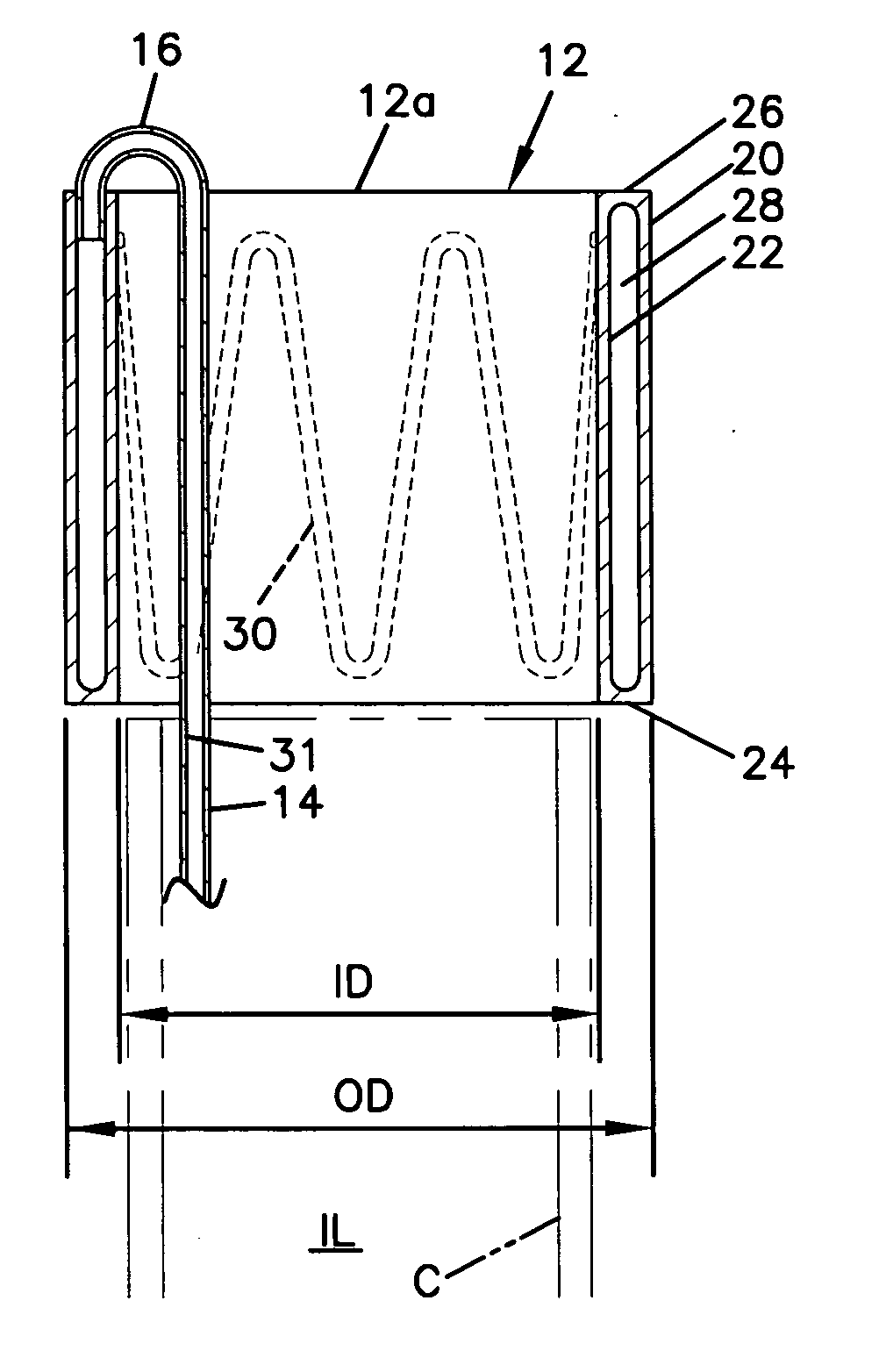
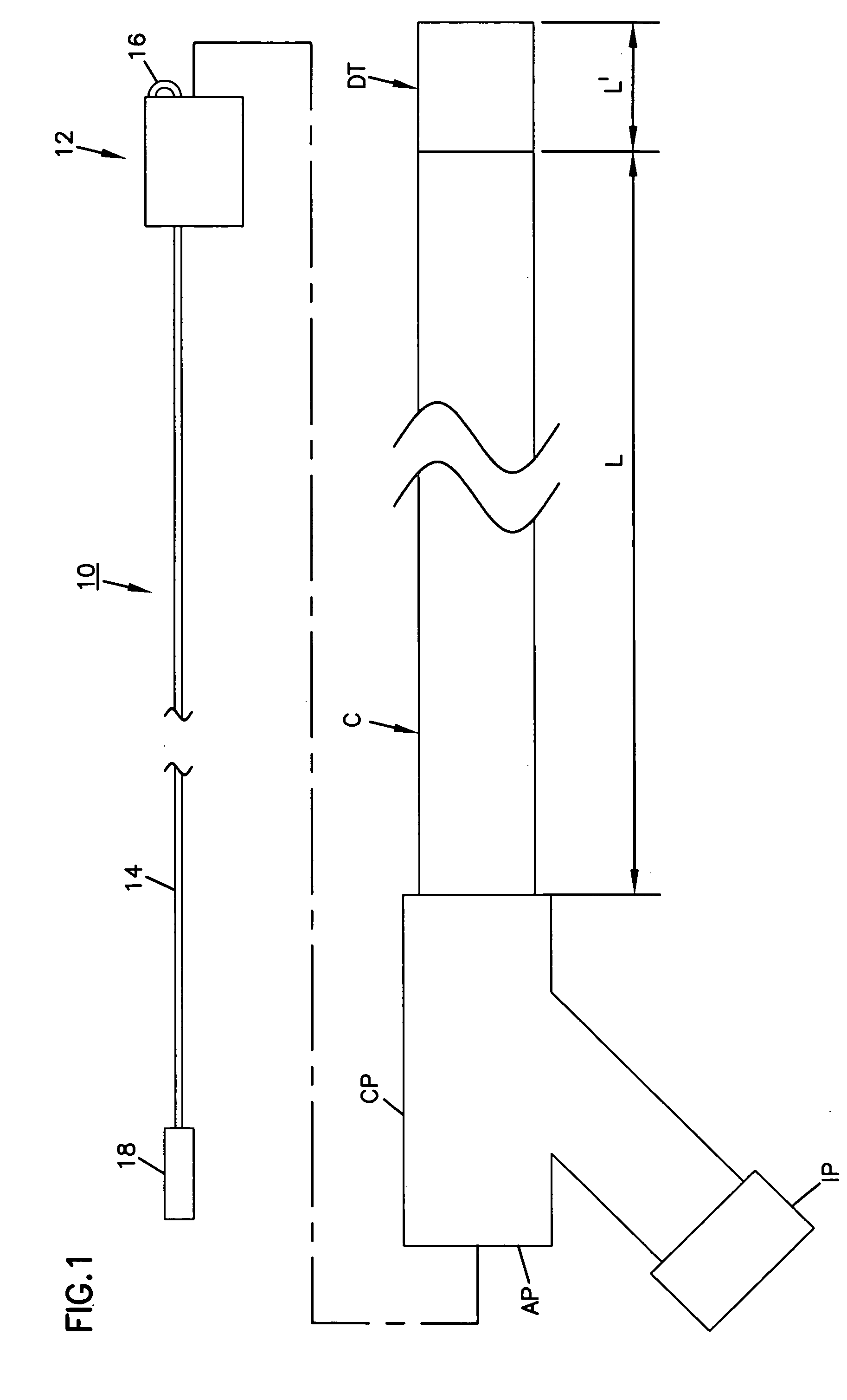
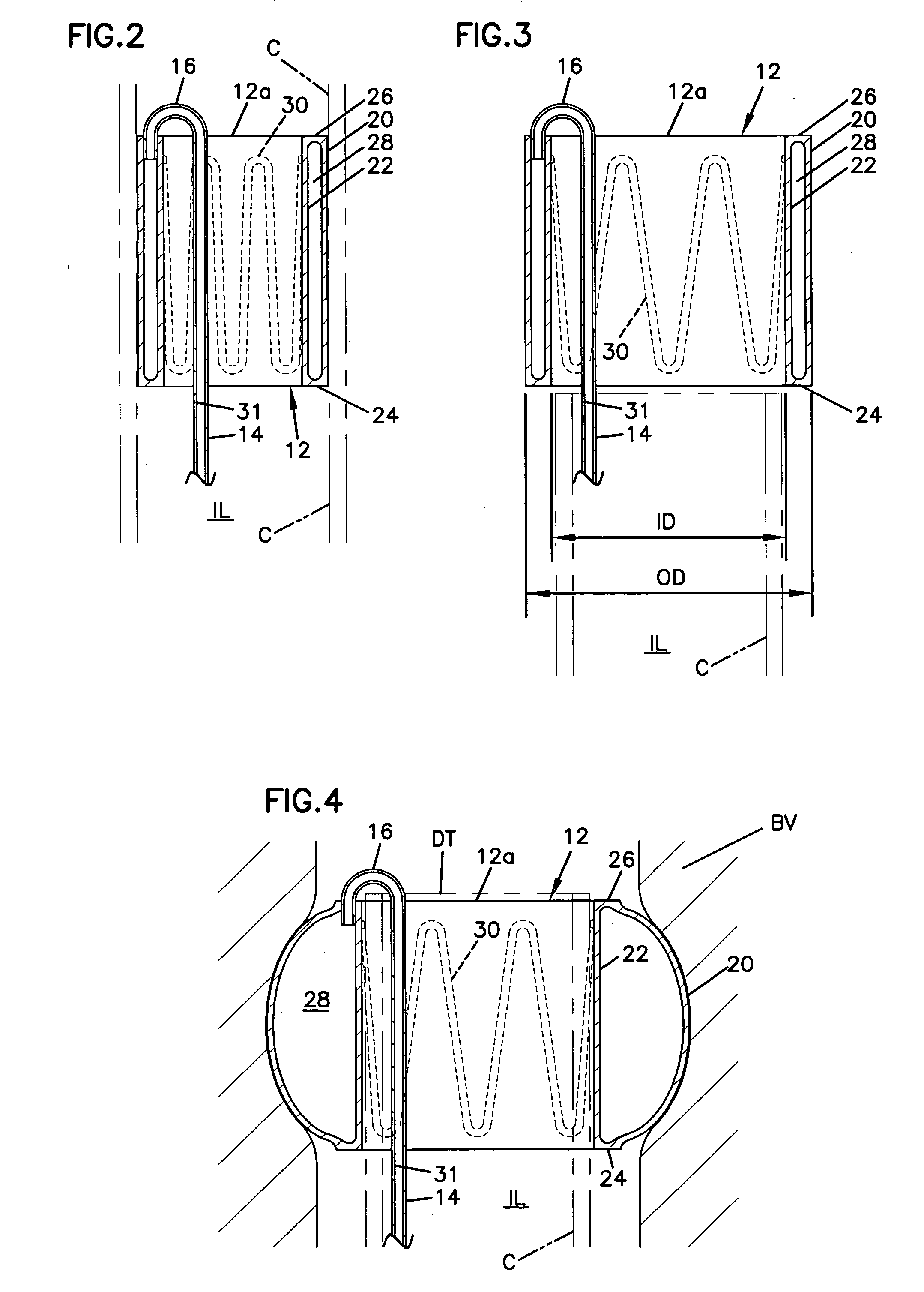
[0053] With initial reference to FIGS. 1-8, a first embodiment of the present invention will now be described. In FIG. 1, an occlusion system 10 is shown for use ...


PUM


Abstract

An occlusion system is disclosed for use with a catheter having a catheter proximal end and a catheter distal end. The catheter has a catheter wall with an outer catheter dimension at the catheter distal end and with the catheter wall defining a catheter lumen with a longitudinal axis extending from the catheter proximal end and through the catheter distal end. The occlusion system includes an occlusion member having an inner wall and an outer wall. The inner wall defines an occlusion member lumen extending throughout an axial length of the occlusion member. The outer wall is expandable between a contracted state with a first transverse dimension and an expanded state with a second transverse dimension. The second transverse dimension is greater than the outer catheter dimension. The occlusion member is sized to be received within the catheter lumen and advanced from the catheter proximal end to the catheter distal end when the outer wall is in the contracted state and with the occlusion member lumen aligned with the catheter lumen. Further embodiments include a rapid-delivery occlusion member advanced along the outer wall of a pre-placed catheter.

Description

CROSS-REFERENCE TO RELATED APPLICATIONS [0001] This application discloses and claims material disclosed in commonly assigned U.S. patent applications Ser. Nos. _______, ________ and ________, filed concurrently herewith in the names of the same inventors as the present application and respectively entitled “VASCULAR CLIP-ON OCCLUSION SYSTEM”, “RAPID BALLOON COUPLING SYSTEM” and “VASCULAR THERAPY DELIVERY SYSTEM” and assigned attorney docket numbers 15059.2US01, 15059.3US01 and 15059.4US01, respectively.BACKGROUND OF THE INVENTION [0002] 1. Field of the Invention [0003] This invention pertains to occlusion systems for use in vascular applications. More particularly, this invention pertains to endovascular devices which can be rapidly deployed during a catheter-based procedure. [0004] 2. Description of the Prior Art [0005] Vascular catheters are well known for accessing treatment sites within a patient's vascular system. Examples of catheter systems can be found, for example, in U.S. ...

Claims


Application Information

Patent Timeline
IPC IPC(8): A61M5/178
CPCA61B17/22032A61B2017/22067A61M25/1025A61M2025/1084A61M25/1034A61M2025/1052A61M2025/1061A61M25/1027
Inventor EUTENEUER, CHARLES LOUISHEKTNER, THOMAS R.
Owner NFOCUS NEUROMEDICAL
Learn More