
Traveling system for a driving vehicle

a technology for driving vehicles and travel systems, applied in electric/magnetic computing, analogue processes for specific applications, instruments, etc., can solve the problems of excessive driving units, difficult to reduce the size of vehicles such as dump trucks, and extremely limited travel area, so as to prevent the increase in reduce the size and weight of driving vehicles

Inactive Publication Date: 2007-08-09
KOMATSU LTD
View PDF10 Cites 2 Cited by
  • Summary
  • Abstract
  • Description
  • Claims
  • Application Information

AI Technical Summary

Benefits of technology

[0009] A main object of the present invention is to provide a traveling system for a driving vehicle which can promote cost reduction for a driving vehicle and also can easily improve the freedom degree on a travel path without causing increase in workload and cost.
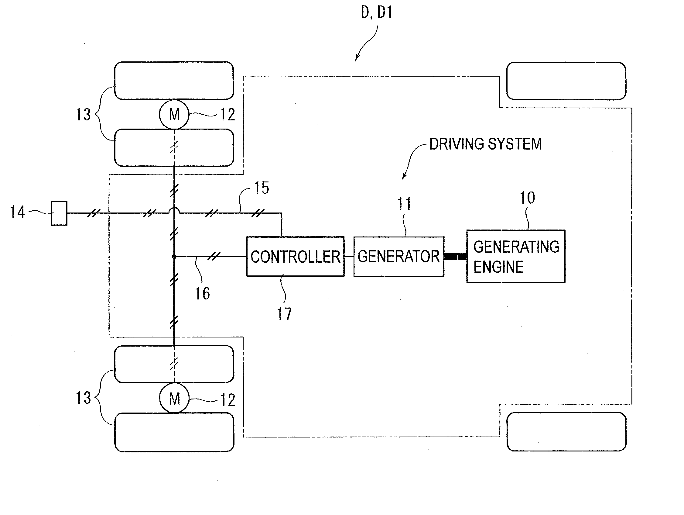
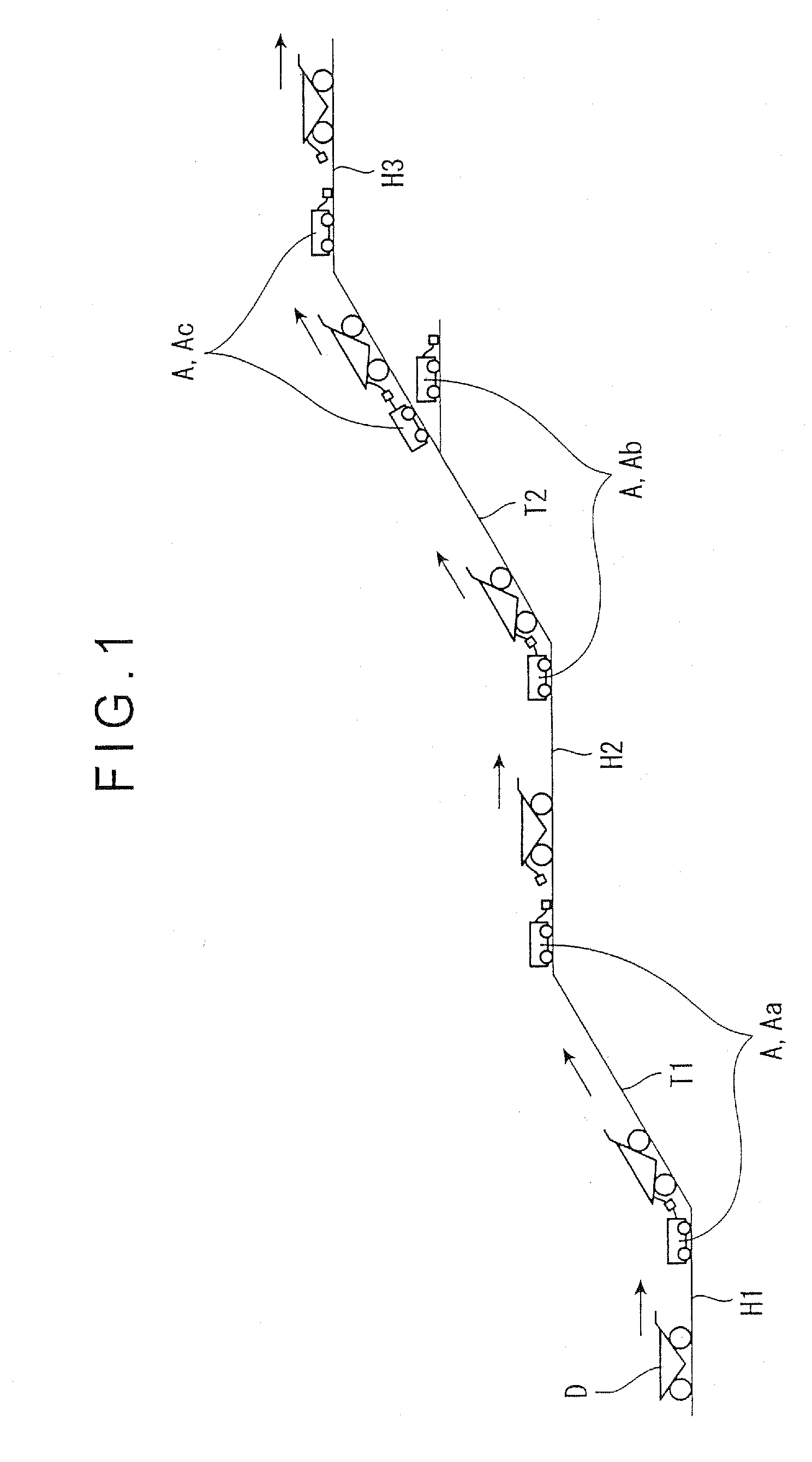
[0012] With the present invention, power is supplied to a driving motor for a driving vehicle from a power supply section according to the necessity, but the power supply section can freely be loaded on or off from a driving vehicle, and therefore, for instance, at a base of a slope, the power supply section may be connected to the driving vehicle to supply auxiliary power only during traveling on an ascending path, and the driving vehicle may be loaded off from the driving vehicle on a descending path or on a horizontal path for traveling by itself. With the configuration, as power is supplied to the driving motor from the power supply section only during the heavy-duty traveling mode so that the driving unit is required only to have the performance adapted to the low-duty traveling, and size reduction of the driving unit can be realized and also the cost reduction is possible. Further as the power supply section is loaded on a driving vehicle and moves together with the driving vehicle, so that a freedom degree of a traveling path for a driving vehicle can substantially be improved. In other words, response to change or extension of a traveling path can easily be performed by separating the power supply section at a prespecified place and setting it in the stand-by state or previously setting the power supply state in the stand-by mode at a prespecified place.
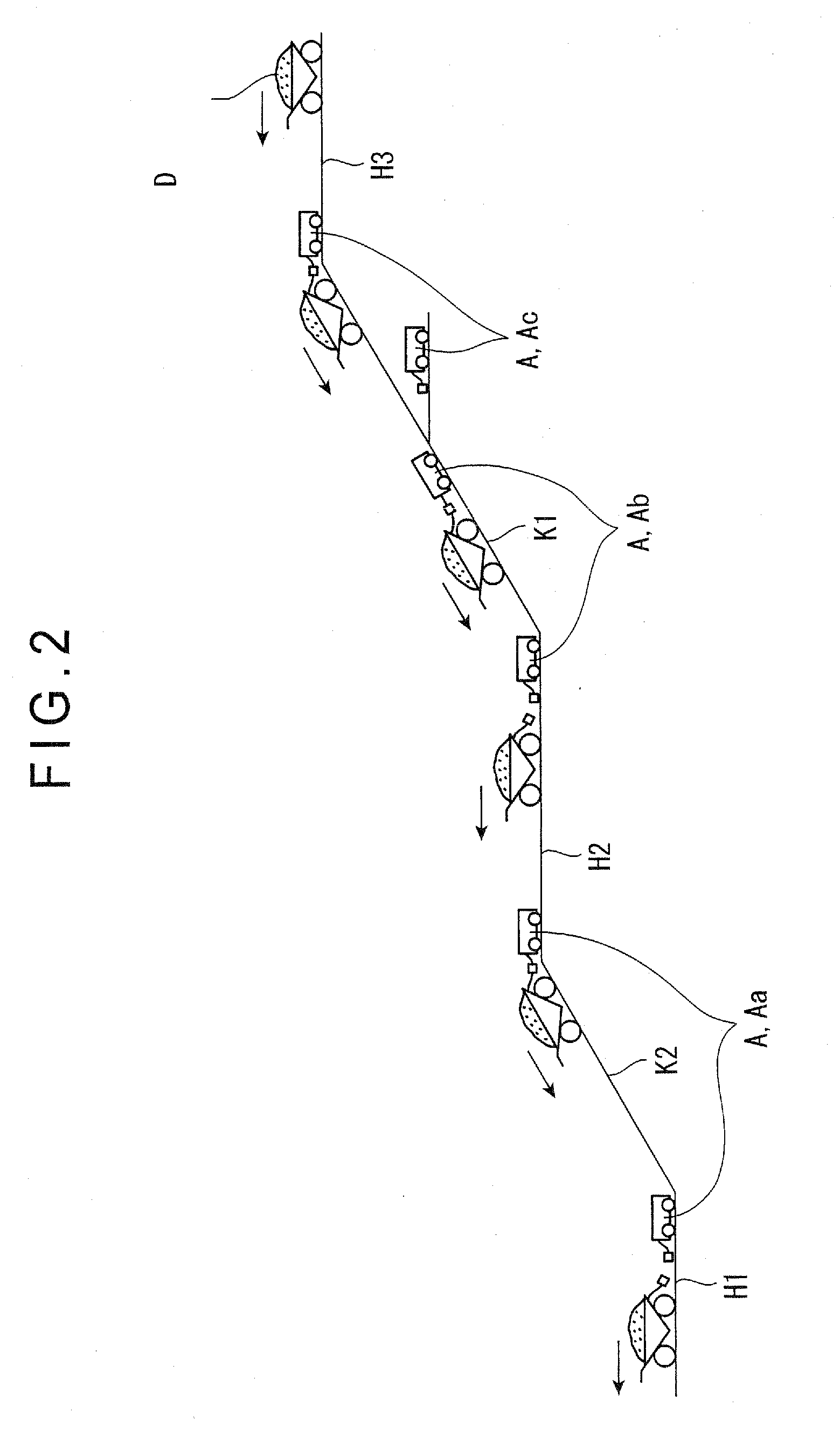
[0014] Also in the conventional type of dump truck having the driving motor, the kinetic energy is converted to the electric energy with the driving motor as described above and the electric energy is used for braking the vehicle. But in that case the regenerated electric energy is further converted to heat by a resistor and is released to the atmospheric air, or is collected through an overhead wire in a case of a trolley dump truck. When an accumulator is provided in a driving vehicle itself there is no way to prevent increase in size and weight of the driving vehicle because of the accumulator. Especially, in a case of a dump truck used on a long ascending path in a mine or the like, sometimes a high-capacity battery (accumulator) is required to be loaded on the driving vehicle, and for the reasons described above, reduction in size and weight of a driving vehicle has been difficult. In contrast, in the present invention, as the regenerated electric energy is accumulated in the accumulator of the power supply section and therefore there is no possibility that the size of the driving vehicle increases to addition when regeneration of the electric energy is performed on a long descending path, by employing the configuration in which the descending path is divided to a plurality of zones and accumulation of the electric energy in the accumulator is performed by using a discrete power supply section in each zone, the discrete accumulator may be of low-capacity, which enables size reduction of the power supply section.

Problems solved by technology

When a dump truck runs on a descending path or a horizontal path, the large output as that required when running on an ascending path is not required, so that the driving unit loaded on the dump truck is rather excessive.
In other words, the driving unit is loaded to respond to the necessity of running up an ascending path without fail, which makes it rather difficult to reduce size of vehicles such as dump trucks.
However, in the technology described in the Patent Publication, as an overhead wire facility provided on the ground is used as a facility for supplying electric power from the outside to a dump truck. there occurs the problem that the dump truck can travel on a path along which the overhead wire facility is installed and the travel area is extremely limited.
In addition the overhead wire facility is required to be installed each time the ascending path is extended, which disadvantageously necessitates large-scale countermeasures associating heavy workload and cost increase.

Method used


Image

  • Traveling system for a driving vehicle
  • Traveling system for a driving vehicle
  • Traveling system for a driving vehicle

Examples


Embodiment Construction

)

[0026] An embodiment of the present invention is described with reference to the related drawings.

[0027]FIG. 1 is a simulated view showing the state in which a dump truck (driving vehicle) D is running up on an ascending path by using a traveling system according to the embodiment. FIG. 2 is a simulated view showing the state in which the dump truck D is running down on a descending path by using the traveling system. In this embodiment, a body of the dump truck D on the ascending path shown in FIG. 1 is empty, while the body of the dump truck D shown in FIG. 2 is filled with cargo, but the present invention is not limited to this configuration and the present invention can respond to a case contrary to that described above.

[0028] Outline of the traveling system is as described below.

[0029] Namely, in the high-duty traveling mode in which a load to the driving unit is high like in a case in which the dump truck D is running on an ascending path an assistant vehicle (power supply...


PUM


Abstract

An assistance vehicle is connected to a dump truck on or at bases of ascending paths and power is supplied as auxiliary power from the assistant vehicle A to a driving motor in the dump truck. Because of this features a driving unit of the dump truck (a generator for supplying power to the driving motor in the dump truck or a generating engine for driving the generator) is required only to have the performance sufficient for running on horizontal paths, which enables size reduction of the driving unit and as a result cost reduction of the dump truck. Further the assistant vehicle is connected to the dump truck and moves together with the dump truck, so that a freedom degree of the dump truck for a traveling path can substantially be improved.

Description

CROSS REFERENCE TO RELATED APPLICATION[0001] The present application is a Divisional Application of U.S. application Ser. No. 10 / 805,664 filed Mar. 18, 2004, which is incorporated herein by reference.BACKGROUND OF THE INVENTION [0002] 1. Field of the Invention [0003] The present invention relates to a traveling system for a driving vehicle. [0004] 2. Description of Related Art [0005] A heavy-duty dump truck with the deadweight of, for instance, 100 tons has a driving engine or a driving motor as a driving unit. In the type of a dump truck having a driving engine, output from the driving engine is transmitted via a transmission to wheels. In the type of dump truck having a driving motor, a generator drives a generating engine, a driving motor is driven by the power generated by the generator, and the wheels are driven by output from the driving motor. The dump trucks as described above are used at many sites such as those for mining development, but the driving unit comprising a driv...

Claims


Application Information

Patent Timeline
Patent Type & Authority Applications(United States)
IPC IPC(8): G06F19/00B60L11/18B60K7/00B60L7/10B60L9/00B60L50/16B62D59/04G06F17/00
CPCB60K6/46B60K6/48B60K6/52B60K6/547Y02T10/6265B60Y2200/14B62D59/04Y02T10/6217Y02T10/6221B60K7/0007Y02T10/62
Inventor OGAWA, SATOSHIURANAKA, KYOJIOKAMOTO, KOICHINAGAI, TAKAO
Owner KOMATSU LTD
Learn More