
Abnormal noise correction verification apparatus

a verification apparatus and noise correction technology, applied in the field of abnormal noise correction verification apparatus, can solve problems such as the degree to which the corrective action was effective, and achieve the effect of easy verification of the degr

Inactive Publication Date: 2007-08-09
NISSAN MOTOR CO LTD
View PDF3 Cites 42 Cited by
  • Summary
  • Abstract
  • Description
  • Claims
  • Application Information

AI Technical Summary

Benefits of technology

[0008]The present invention was created to solve the abovementioned problems. One object of the present invention is to provide an abnormal noise correction verification apparatus and an abnormal noise correction verifying method that can easily verify the degree to which corrective action was effective after taking such corrective action at the problem location.

Problems solved by technology

Consequently, there is not only a problem in that corrective action to address the causes of abnormal noise takes time, but there is also a problem in that it requires operator expertise to determine the degree to which the corrective action was effective.

Method used


Image

  • Abnormal noise correction verification apparatus
  • Abnormal noise correction verification apparatus
  • Abnormal noise correction verification apparatus

Examples


first embodiment

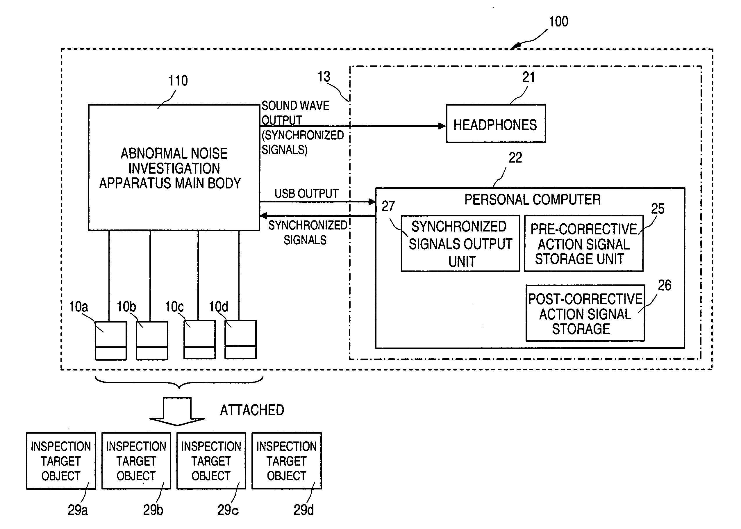
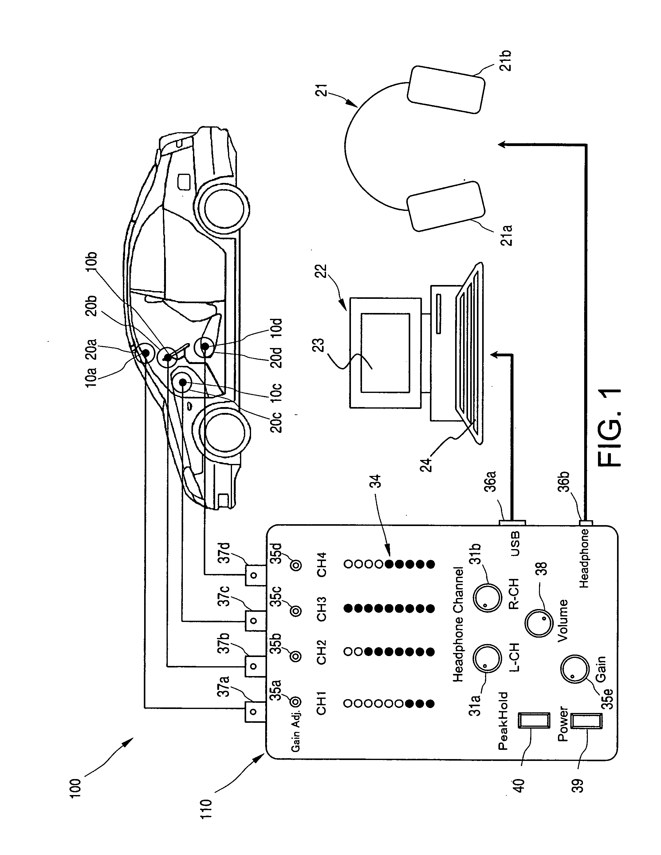
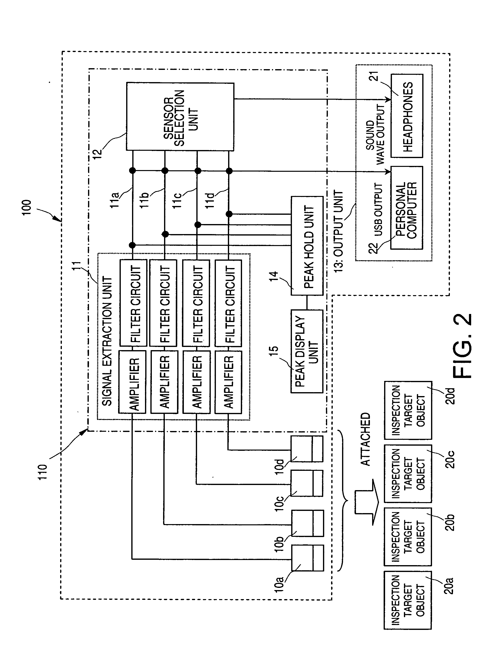
[0028]Before describing the embodiments of the present invention in detail, an overview of an abnormal noise investigation will be given first in order to facilitate understanding of an abnormal noise correction verification apparatus 100 and method according to the present invention. FIG. 1 serves to explain the general constitution of the abnormal noise correction verification apparatus 100 according to the present invention, and illustrates usage conditions for searching for a part where abnormal vibrations of a vehicle are generated. As shown in FIG. 1, the abnormal noise correction verification apparatus 100 basically includes a main abnormal noise investigation unit 110, a plurality of vibration sensors 10a to 10d, a personal computer 22, and a pair of headphones 21.

[0029]The main abnormal noise investigation unit 110 has a plurality of sensor connection terminals 37a to 37d and a plurality of gain adjustment knobs 35a to 35e. The vibration sensors 10a to 10d are connected to ...

second embodiment

[0123]In addition, the abnormal noise correction verification apparatus 200 in accordance with a second embodiment will be explained with reference to the usage condition shown in FIG. 8, which is for a case of searching for abnormal vibrations in a rear suspension. Thus, the explanatory diagram shown in FIG. 11, which relates to the output of the synchronized signals, also applies to the abnormal noise correction verification apparatus 200 and its abnormal noise correction verifying method.

[0124]The displacement detection unit 28 detects the displacement of the vehicle in the vertical direction on the prescribed route, and functions as a displacement detecting component. The displacement detection unit 28 functions as a displacement calculating component that calculates the displacement of an inspection target object in the vertical direction based on, for example, an integration calculation program that calculates displacement based on an acceleration signal.

[0125]The displacement...


PUM


Abstract

An abnormal noise correction verification apparatus is provided that can easily verify the effectiveness a corrective action with respect to an abnormal noise being generated. The apparatus has at least one vibration sensor, which detect vibrations of the vehicle. The apparatus extracts a signal in a specific frequency band for the vibrations detected from the vibration sensor. The apparatus stores a pre-corrective action signal extracted from the vibration sensor, which is from before eliminating a cause of abnormal noise, and a post-corrective action signal extracted from the vibration sensor, which is from after eliminating the cause of abnormal noise. Both pre-corrective action signal and the post-corrective action signal were detected under identical travel conditions by the vibration sensor. The apparatus then synchronizes and separately outputs the pre-corrective action signal and the post-corrective action signal for comparison.

Description

CROSS-REFERENCE TO RELATED APPLICATIONS[0001]This application claims priority to Japanese Patent Application No. 2006-021443 filed on Jan. 30, 2006. The entire disclosure of Japanese Patent Application No. 2006-021443 is hereby incorporated herein by reference.BACKGROUND OF THE INVENTION[0002]1. Field of the Invention[0003]The present invention generally relates to an abnormal noise correction verification apparatus as well as an abnormal noise correction verifying method. More specifically, the present invention relates to an abnormal noise correction verification apparatus and an abnormal noise correction verifying method that compare vibrations generated by a vehicle before and after eliminating the causes of abnormal noise in order to verify whether the action taken to correct the abnormal noise has been effective.[0004]2. Background Information[0005]If, for example, abnormal vibrations are generated by an inspection target object, such as a constituent part of a vehicle, then a...

Claims


Application Information

Patent Timeline
Patent Type & Authority Applications(United States)
IPC IPC(8): G01L7/00G01M17/00
CPCG01M13/028G01M17/007G01M13/045
Inventor TANAKA, TSUTOMUKAWANO, JUNICHIYOSHIDA, TOSHIAKIAMAKASU, JUNICHI
Owner NISSAN MOTOR CO LTD
Learn More