Music practice supporting appliance
a technology of supporting appliance and music, which is applied in the field of music practice supporting appliance, can solve the problems of difficulty in satisfying the demand for recognition of minute shifts in musical intervals as in the practice of musical instruments and vocal music, and the conventional technique has another problem, so as to achieve easy grasping, effective music practice, and easy play of music
- Summary
- Abstract
- Description
- Claims
- Application Information
AI Technical Summary
Benefits of technology
Problems solved by technology
Method used
Image
Examples
first embodiment
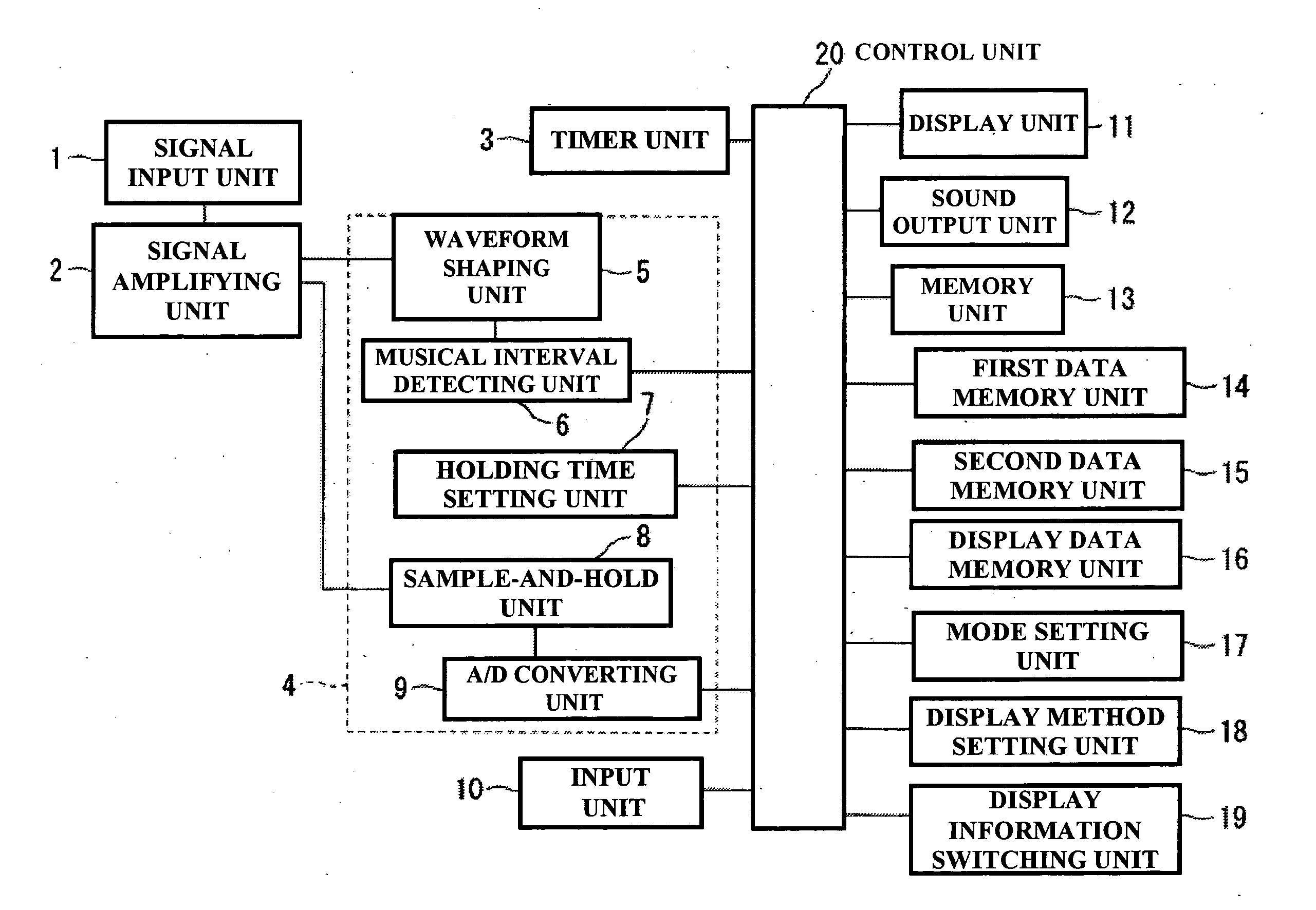
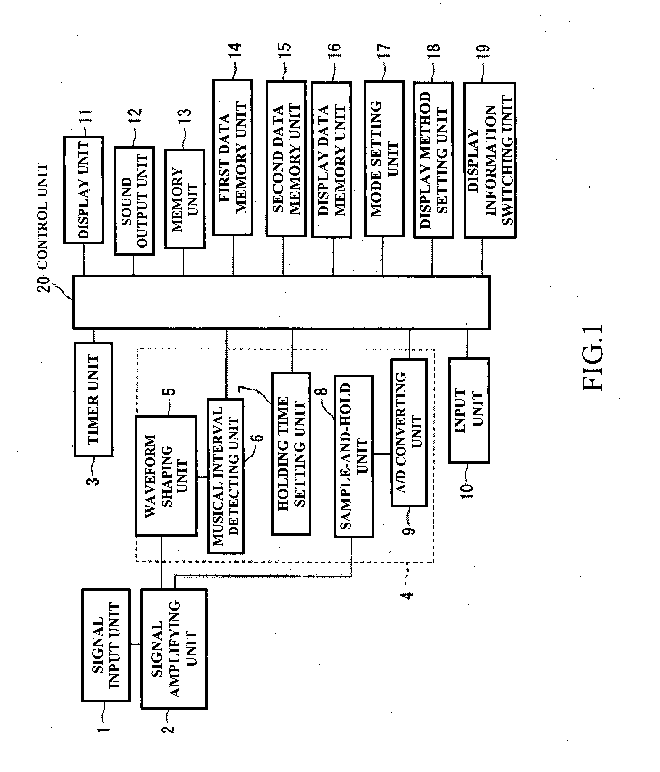
[0045]FIG. 1 is a schematic block diagram for showing a music practice supporting appliance according to the present invention.
[0046] A signal input unit 1 receives an input of sounds of musical instruments and converts the inputted sounds into electric signals. The signal input unit 1 may employ, for example, a microphone, a piezoelectric element, and a vibration sensor, which convert mechanical vibrations into electric signals. However, output signals derived from a microphone, a piezoelectric element, a vibration sensor, and the like are extremely small, and therefore need to be amplified. A signal amplifying unit 2 amplifies an input signal inputted to the signal input unit 1, and then, outputs the amplified input signal to a waveform shaping unit 5 and a sample-and-hold unit 8. The signal amplifying unit 2 converts the input signal inputted through the signal input unit 1 into such a signal having a voltage level suitable to be processed in the waveform shaping unit 5 and the s...
second embodiment
[0064]FIG. 3 is a block diagram for indicating a signal processing unit of the present invention. A vibration pick-up unit 23 is mounted to a musical instrument, while a piezoelectric element is arranged in the vibration pick-up unit 23. In the vibration pick-up unit 23, the piezoelectric element converts vibrations produced when the musical instrument is played into electric signals in response to the vibrations, and then, outputs the electric signals. An input signal amplifying unit 24 amplifies an electric signal outputted from the vibration pick-up unit 23. The input signal amplifying unit 24 inputs the amplified signal to an antialiasing filter unit 25. In order that aliasing does not occur when an A / D converting operation is carried out, the amplified signal is filtered by an antialiasing filter of the antialiasing filter unit 25 before being A / D-converted. In other words, the filtering operation is carried out in order to remove signals having frequencies equal to or higher t...
third embodiment
[0065]FIG. 4 is a block diagram for showing the present invention. A musical sound acquiring unit 28 corresponds to a signal input unit, and receives sounds of a musical instrument so as to convert the inputted sounds into electric signals. A converted input signal is outputted to an input waveform processing unit 29. The input waveform processing unit 29 executes various signal process operations such as amplifying operation, waveform shaping operation, and antialiasing filtering operation with respect to the input signal, and then, outputs the processed signal to a microcomputer 33 and an A / D converting unit 32. The A / D converting unit 32 converts the analog signal into a digital signal, and outputs the converted data to the microcomputer 33. The microcomputer 33 controls overall operations of the music practice supporting appliance based upon programs previously stored in the ROM 30. The microcomputer 33 calculates a musical interval based upon a signal inputted through the input...
PUM
 Abstract
Description
Claims
Application Information
 - R&D
- Intellectual Property
- Life Sciences
- Materials
- Tech Scout
- Unparalleled Data Quality
- Higher Quality Content
- 60% Fewer Hallucinations
Browse by: Latest US Patents, China's latest patents, Technical Efficacy Thesaurus, Application Domain, Technology Topic, Popular Technical Reports.
© 2025 PatSnap. All rights reserved.Legal|Privacy policy|Modern Slavery Act Transparency Statement|Sitemap|About US| Contact US: help@patsnap.com


