Direction change device

a technology of a direction change device and a change device, which is applied in the direction of vehicle maintenance, vehicle-manoeuvring devices, transportation and packaging, etc., can solve the problem that objects cannot be transported while the waiting time is over, and achieve the effect of shortening the changing tim

Inactive Publication Date: 2007-08-16
ASYST SHINKO INC
View PDF12 Cites 30 Cited by
  • Summary
  • Abstract
  • Description
  • Claims
  • Application Information

AI Technical Summary

Benefits of technology

[0006]An advantage of an aspect of the invention is that it provides a direction change device capable of shortening a changing time.
[0018]In such a configuration, after the direction of the work is changed to carry out the work, the next work can be ready to change the direction thereof in a short time. Specifically, by equalizing the vertical positions of the first transport passage and the transport rail and disposing the second transport passage below the first transport passage in a vertical position, the work on the transport rail can be carried out to the first transport passage without obstructing the second transport passage. Additionally, when the work is carried out from the transport rail to the first transport passage, the transporting direction of the work can be changed by 90° by rotating the first and second transport passage by about 90°. After the work is removed from the first transport passage, the work on the transport rail can be carried out to the second transport passage by exchanging the respective vertical positions of the first and second transport passages.
[0019]That is, when only one transport passage is provided in the rotating unit, it is necessary to move the transport passage back to a position where it can receive the work from the transport rail after the work is removed from the transport passage. However, as described above, by exchanging the respective vertical positions of the two transport passages, it is possible to shorten an idle time.
[0023]In such a configuration, since the work is transported by rotation of the transport rail and the rollers provided along both sides of the transport passages, the work can be transported without interrupting the transporting direction of the work.

Problems solved by technology

As a result, since the director drive rail is required to come back the initial location at each time of the direction change, the article cannot be transported while the waiting time.

Method used


Image

  • Direction change device
  • Direction change device
  • Direction change device

Examples


modification embodiment

[0066]The above-described preferred embodiment of the invention is described, but the invention is not limited to the described embodiment. The invention may be modified in various forms without departing from the gist of the invention. Further, according to the embodiment, the operation and advantage of the configuration of the invention is described above, but the operation and advantage are just an example and the invention is not limited thereto.

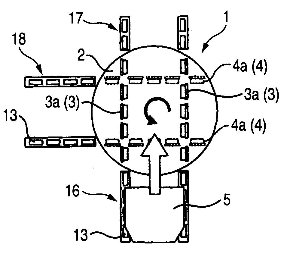
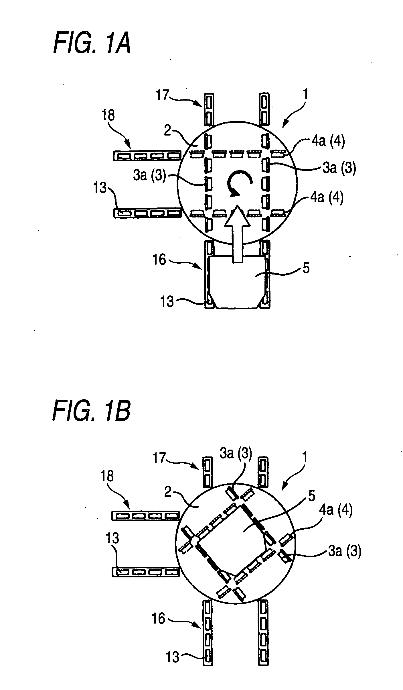
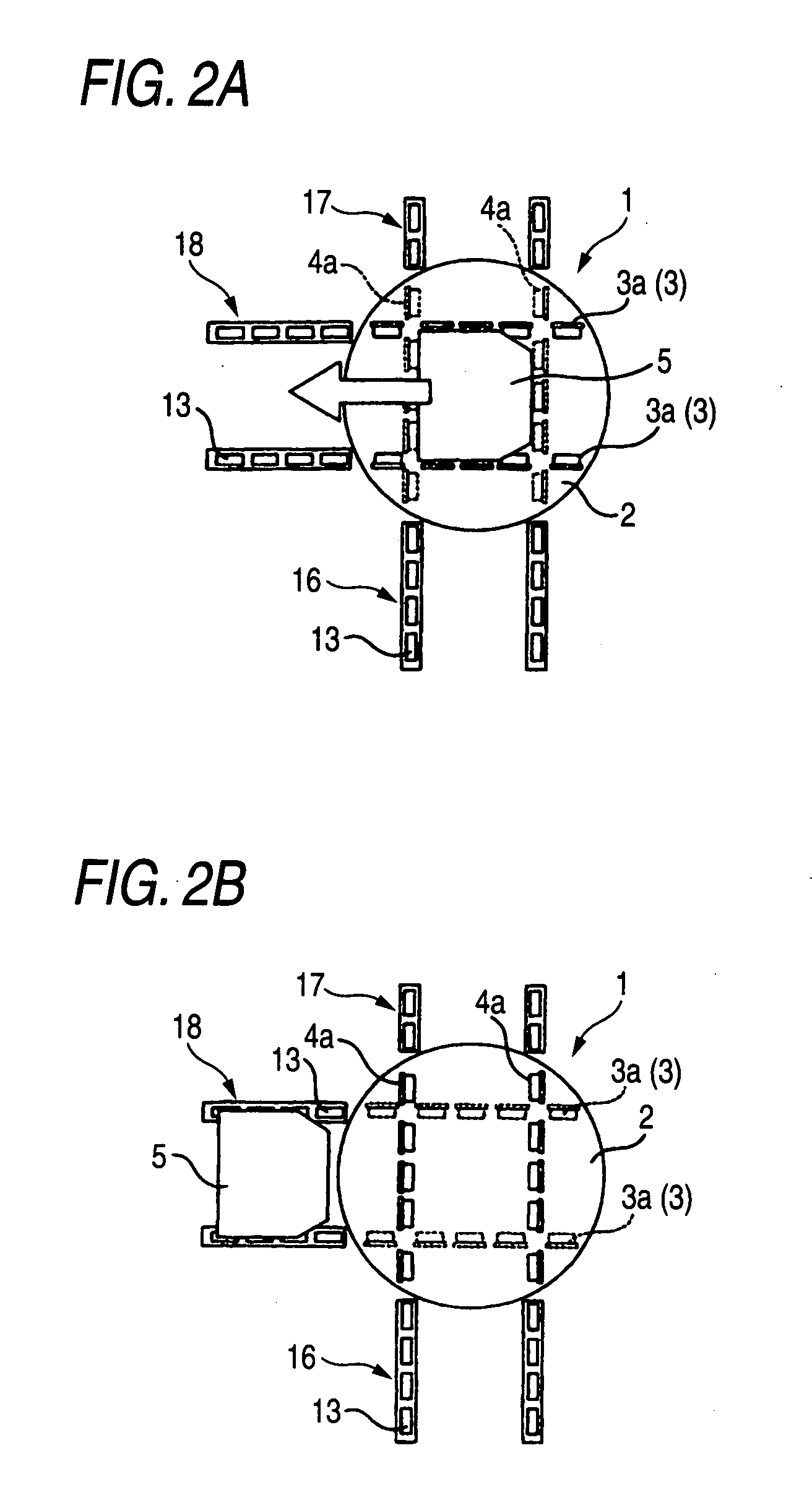
[0067]For example, when the FOUP 5 is placed on the first transport passage 3, the rotation of the roller 3a of the first transport passage 3 stops and the turn table 2 rotates according to the embodiment. However, while the FOUP S is transported, the turn table 2 may rotate. In this case, since the FOUP 5 can be transported from the first transport rail 16 to the third transport rail 18 without stopping the FOUP 5 on the first transport passage 3, a time required to change the direction may be shortened more. Additionally, it is describ...


PUM


Abstract

A direction change device includes first and second transport passage 3, 4, in which one of the transport passages is disposed at the same vertical position as that of the first transport rail 16, the other is disposed below the one, a rotating unit 22 rotating the transport passages 3, 4 about their central points, a lift unit 23 lifting the transport passages 3, 4 in a vertical direction and a control unit 21. The control unit 21 controls such that when the FOUP 5 is carried out from the transport rail 16 to the transport passage disposed at the same vertical position as that of the transport rail 16, rotating the transport passages 3, 4 by about 90°, carrying out the FOUP 5 from one of the transport passages, and exchanging the respective vertical positions of the first and second transport passages 3, 4.

Description

BACKGROUND OF THE INVENTION[0001]1. Field of the Invention[0002]The invention relates to a direction change device which changes a transporting direction of an article.[0003]2. Description of Related Art[0004]As a changing means used in semiconductor manufacturing, liquid crystal manufacturing, factory automation (FA), and the like, a transport system disclosed in Japanese Patent Unexamined Publication JF-T-2003-506289 is exemplified. In the transport system disclosed in JP-T-2003-506289, rotating wheels are provided so as to be projected from upper surfaces of a pair of rails, and an article placed on the wheels is transported along the rails by rotation of the wheels. Additionally, in JP-T-2003-506289, in a rail provided so as to be perpendicular to each other, a director drive rail which changes direction of the article is provided. The director drive rail is provided so as to rotate between two rails perpendicularly disposed to each other and can change the direction of the arti...

Claims


Application Information

Patent Timeline
Patent Type & Authority Applications(United States)
IPC IPC(8): B61J1/00
CPCB61J1/00H01L21/67715H01L21/6773B65G43/08
Inventor KYUTOKU, SENZOTSUBAKI, TATSUOMURATA, MASANAO
Owner ASYST SHINKO INC
Why Eureka
Try Eureka