
Piston ring having improved scuffing, cracking and fatigue resistances, and its production method, as well as combination of piston ring and cylinder block

a technology of scuffing, cracking and fatigue resistance, which is applied in the field of piston rings, can solve the problems of scuffing of the piston ring and the liable roughness of the surface of the block by grinding, and achieve the effect of suppressing the initiation and propagation of cracks and reducing the size of grain boundary lamellar compounds

Inactive Publication Date: 2007-08-16
TAKAHASHI JUNYA +3
View PDF1 Cites 24 Cited by
  • Summary
  • Abstract
  • Description
  • Claims
  • Application Information

AI Technical Summary

Benefits of technology

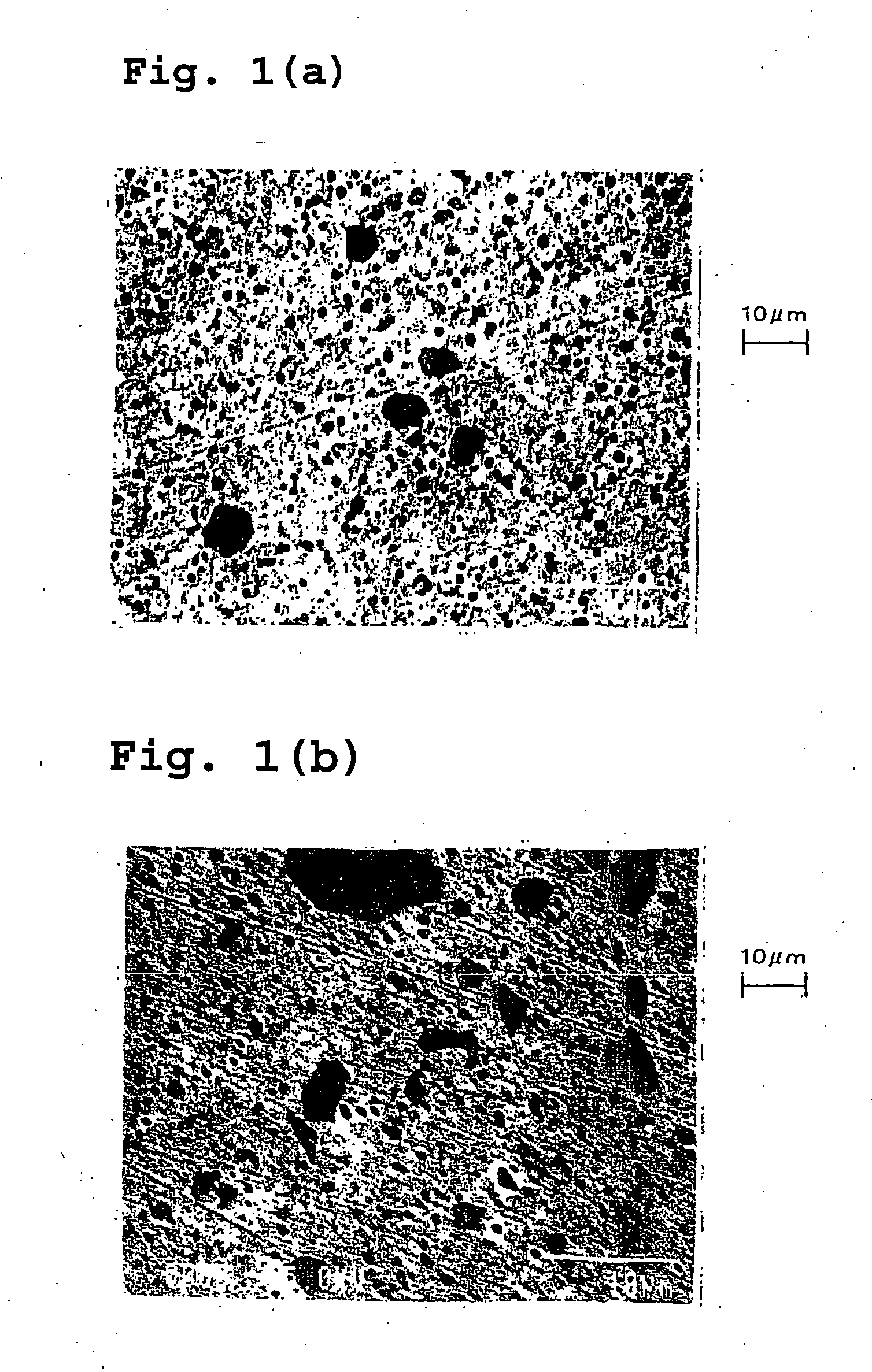
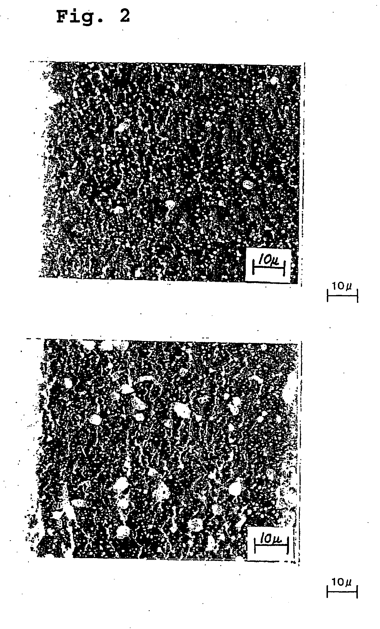
[0019] In the high chromium martensitic stainless steel with nitriding, the microstructure of the nitriding layer generally shows mainly hard nitrides dispersed in the tempered martensite matrix. The mechanism of scuffing is strongly dependent upon the microscopic unevenness on the sliding surface. In the nitriding layer, hard particles disperse in the relatively soft matrix. The microscopic unevenness is, therefore, defined by the size and dispersion state of the hard particles. When the cross section of the surface layer having such structure is observed, the following is apparent. The convex hard particles are brought into contact with an opposite sliding surface, while the relatively soft matrix is relatively concave. The lubricating oil retained in the concave portions is subjected to pressure during sliding. Frequency of the entire direct contact of the steel with nitriding and the opposite member is low, since the steel with nitriding has the microstructure as described above. As a result, the contact pressure between both sliding members is decreased. In addition, the oil is fed to the convex portions mentioned above. The scuffing can, therefore, be prevented.
[0044] In the present invention, high hardness of from Hv 900 to 1400 is obtained up to a satisfactory depth from the surface by the nitriding treatment for a relatively short period of time. This feature is attributable to the relatively fine γ crystal grains formed at low quenching temperature and thus to the increase of the grain boundaries which are the main diffusion passages of N during the nitriding treatment.

Problems solved by technology

This phenomenon results in scuffing of the piston ring.
Specifically, in the case of the cast iron monolithic cylinder block having a non-uniform structure as described above, the surface of this block is liable to be roughened by the grinding.

Method used


Image

  • Piston ring having improved scuffing, cracking and fatigue resistances, and its production method, as well as combination of piston ring and cylinder block
  • Piston ring having improved scuffing, cracking and fatigue resistances, and its production method, as well as combination of piston ring and cylinder block
  • Piston ring having improved scuffing, cracking and fatigue resistances, and its production method, as well as combination of piston ring and cylinder block

Examples


examples 1-11 (

J1-J11) and COMPARATIVE EXAMPLES 1-8 (H1-H8)

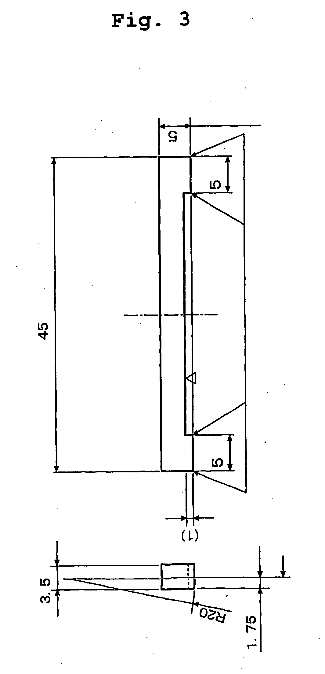
[0053] The high chromium martensitic stainless steels having a composition shown in Table 1 were melted in an amount of 10 kg in a vacuum induction melting furnace. However, less than 0.2% of N was added to the steel during melting under the normal pressure, while 0.2% or more of N was added to steel during melting under pressure N2 gas atmosphere. Wire material having 12 mm of diameter was obtained by hot working. After acid cleaning, spheroidizing annealing was carried out at 750° C. for 10 hours. A wire having a rectangular cross section of 3.5 mm×5.0 mm was produced through working steps. The wire was passed through a quenching furnace (Ar protective atmosphere) and a tempering furnace (Ar protective atmosphere). The air quenching was carried out from 930° C. after keeping approximately 10 minutes at that temperature. The tempering was carried out at 620° C. for approximately 25 minutes. The wires were cut into 50 mm long samples for t...

examples 12-14 (

J12-J14) AND COMPARATIVE EXAMPLES 9-11 (H9-H11)

[0065] The materials having the chemical composition of Example 1 were worked into a wire and air quenched from the temperature shown in Table 4. The gas nitriding treatment was carried out by the same method as in Example 1. The microstructure of the nitriding layer was quantitatively analyzed. The results are shown in Table 4.

TABLE 4Longest LengthHard Particles of Slidingof GrainNitriding LayerBoundaryAverageLargestCompound inQuenchingParticleParticleAreaCross SectionTemperatureDiameterDiameterRatioof Nitriding(° C.)(μm)(μm)(%)Layer (μm)H9*8000.3515.414J128700.5519.411J139201.3618.515J149801.8617.418H1010302.3914.731H1110802.81111.549

*The hardness of the nitriding layer of Comparative Example 9 (H9) was low of Hv 860.


PUM

PropertyMeasurementUnit
particle sizeaaaaaaaaaa
size(lengthaaaaaaaaaa

Abstract

A piston ring having improved scuffing resistance, cracking resistance and fatigue resistance, consists of a high-chromium martensitic stainless steel and a sliding nitriding layer formed on the surface of said steel. The stainless steel consists of C: 0.3 to 1.0%; Cr: 14.0 to 21.0%, N: 0.05 to 0.50%, at least one of Mo, V, W and Nb: 0.03 to 3.0% in total, Si: 0.1 to 1.0%, Mn 0.1 to 1.0%, P: 0.05% or less, S: 0.05% or less, the balance being Fe and unavoidable impurities. The sliding nitriding layer comprises on its surface hard particles mainly consisting of nitrides in a range of from 0.2 to 2.0 μm of average particle size, 7 μm or less of the longest diameter, and from 5 to 30% in area ratio.

Description

[0001] This application is a continuation of U.S. patent application Ser. No. 10 / 333,326 which entered the U.S. national stage on Jan. 17, 2003, as a 371 of PCT / JP01 / 06127 filed Jul. 16, 2001, which claims priority based on Japanese patent application No. 2000-216255 filed Jul. 17, 2000, each of which is incorporated herein by reference.BACKGROUND OF INVENTION [0002] 1. Technical Field [0003] The present invention relates to a piston ring used in an internal combustion engine, particularly, a piston ring consisting of high chromium martensitic stainless steel with nitriding, having improved scuffing resistance (seizure resistance), cracking resistance (failure resistance) and fatigue resistance. The present invention is also related to a production method of the piston ring. [0004] 2. Background Technique [0005] Along with recent demands for low fuel consumption, weight reduction and high performance of internal combustion engines, the piston rings are thinned to reduce weight and t...

Claims


Application Information

Patent Timeline
Patent Type & Authority Applications(United States)
IPC IPC(8): C23C8/26C21D8/06C21D9/40F02F5/00C21D9/52C22C38/00C22C38/18C22C38/22C22C38/24C22C38/26C22C38/60F16J9/26
CPCC21D8/065C21D9/40C21D2211/008C22C38/001C23C8/26C22C38/18C22C38/22C22C38/24C22C38/26C22C38/002
Inventor TAKAHASHI, JUNYAONUKI, TORUINOUE, SHIGEOSASAKURA, MITSUTAKA
Owner TAKAHASHI JUNYA
Learn More