Storage control device and storage system
a storage control device and control device technology, applied in the direction of static indicating devices, image memory management, instruments, etc., can solve the problems of increasing cost, increasing complexity, and not being able to stop the storage control device, and achieve the effect of simplifying the structur
- Summary
- Abstract
- Description
- Claims
- Application Information
AI Technical Summary
Benefits of technology
Problems solved by technology
Method used
Image
Examples
embodiment 1
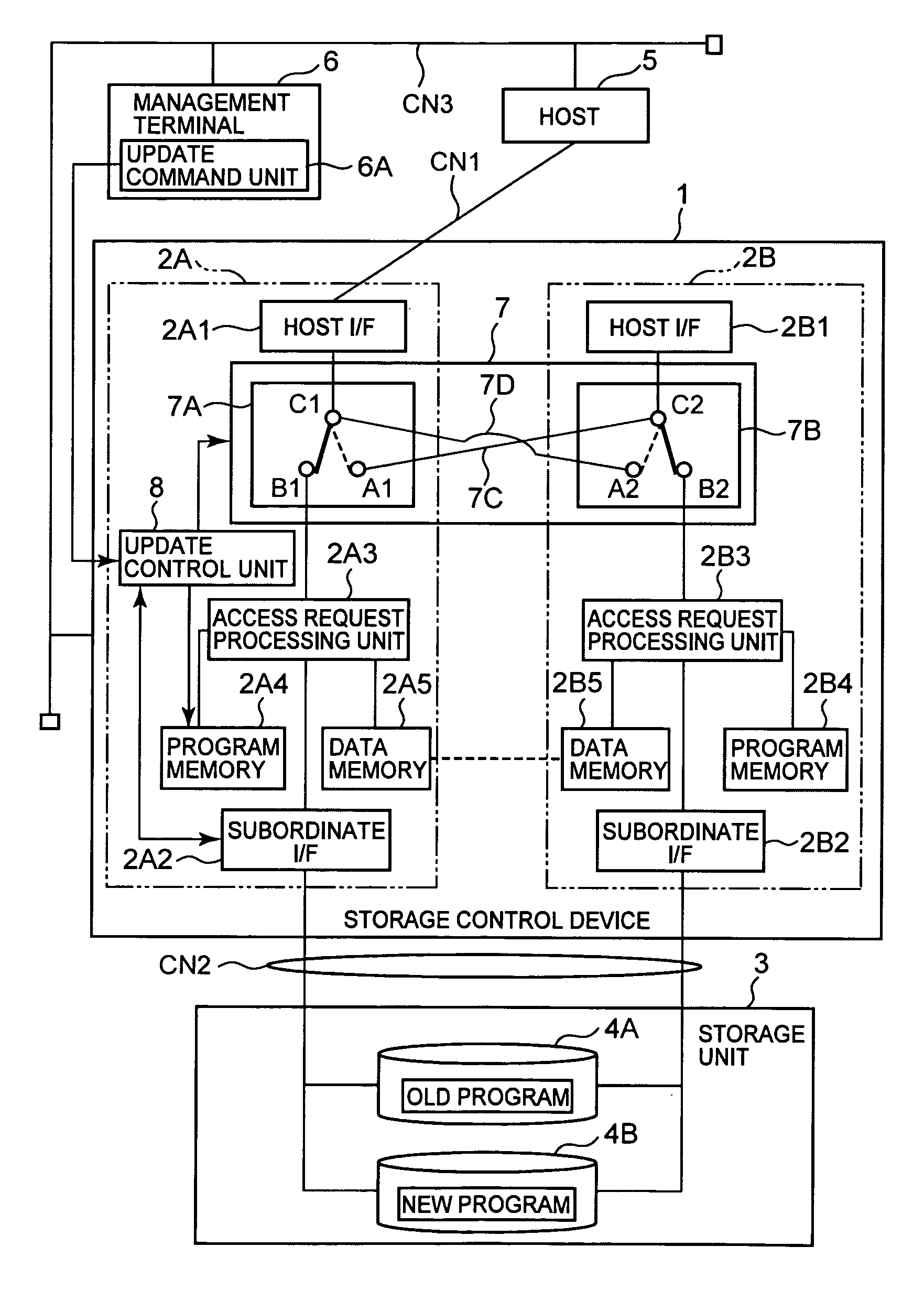
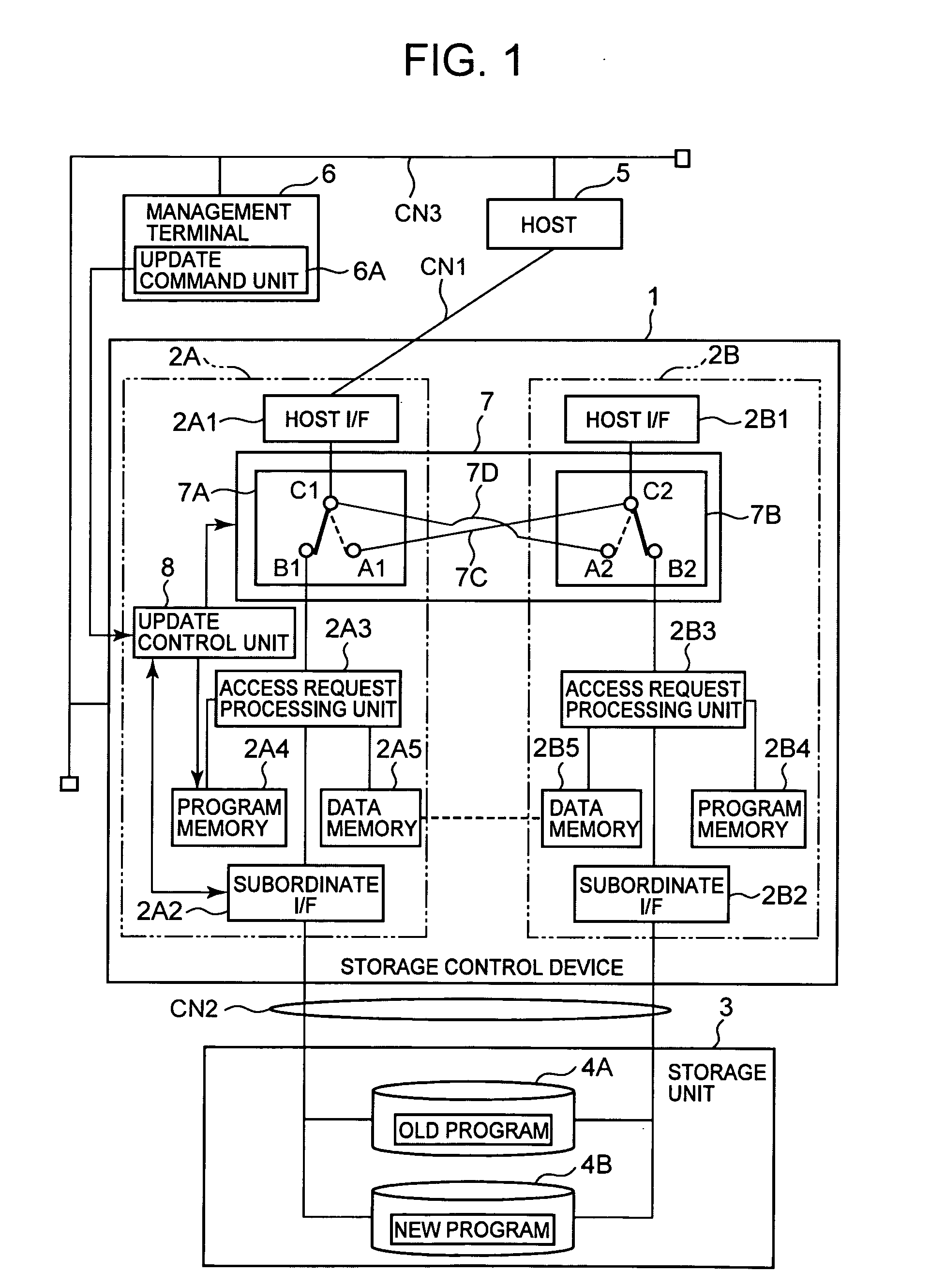
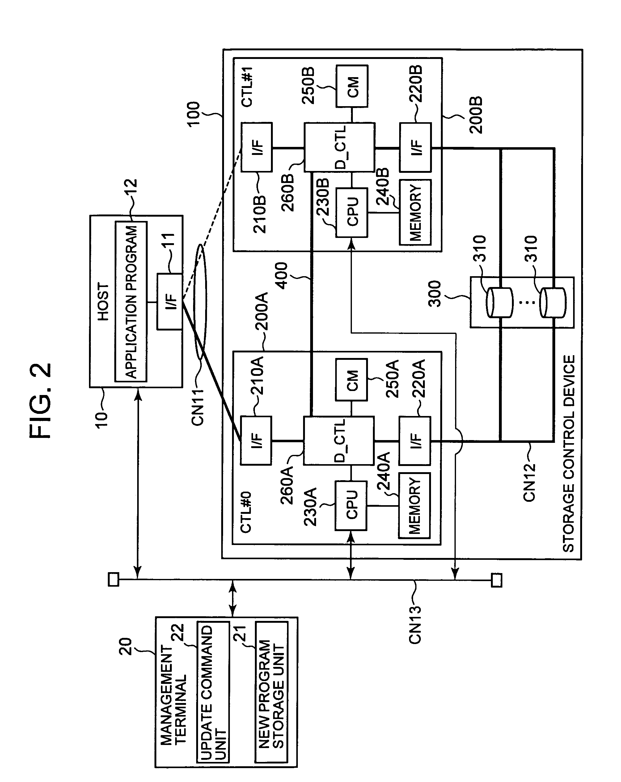
[0067]FIG. 2 is an explanatory figure showing the overall structure of a storage system according to this first embodiment. This storage system, for example, may comprise a storage device 100, a host 10, and a management terminal 20. The storage control device 100 corresponds to the storage control device 1 in FIG. 1. Furthermore, the host 10 corresponds to the host 5 in FIG. 1, while the management terminal 20 corresponds to the management terminal 6 in FIG. 1.
[0068]The host 10 is a computer device such as, for example, a personal computer, a server computer, a main frame, an engineering work station, or the like. This host 10, for example, may comprise a communication I / F 11 which consists of a HBA (Host Bus Adapter) or a network card or the like, and an application program 12. Although, apart from these elements, there may also be included an OS or a user interface or the like, description thereof will here be omitted. The I / F 11 is connected to the storage control device 100 via...
embodiment 2
[0136]Next, a second embodiment of the present invention will be explained with reference to FIGS. 12 and 13. Each of the embodiments described below, including this second embodiment, may be considered as a variant of the first embodiment. In the following description of these various embodiments, duplication of explanation will be omitted, and the discussion will focus on the distinguishing portion of each embodiment.
[0137]In this second embodiment, the execution of program updating from the host 10A is commanded by a so-called inband method. In the first embodiment described above, notification of update commands and the like was provided from the management terminal 20 to the storage control device 100 via the network for management CN13. Such a method is termed an “out-of-band” method. In this embodiment, instead, the updating of programs is commanded using the network CN11 for data input and output.
[0138]FIG. 12 is an explanatory figure showing the overall structure of a stora...
embodiment 3
[0146]A third embodiment of the present invention will now be explained with reference to FIG. 14. In this third embodiment, the management function 15 for managing the updating of the program is provided to the host 10B. However, the point of difference from the second embodiment described above, is that the updating commands and so on are transmitted to the storage control device 100 via the network for management CN13.
[0147]FIG. 14 is an explanatory figure showing the overall structure of a storage system according to this third embodiment. The host 10B is provided with a management function 15. To this management function 15, there are provided a new program storage unit 16 for storing the new program, and an update command unit 17 for commanding the updating of the program. And this management function 15 is connected to the network for management CN13 via a LAN I / F 18. The operation of this embodiment is the same as that of the first embodiment. However, the exchange of inform...
PUM
 Abstract
Description
Claims
Application Information
 - R&D
- Intellectual Property
- Life Sciences
- Materials
- Tech Scout
- Unparalleled Data Quality
- Higher Quality Content
- 60% Fewer Hallucinations
Browse by: Latest US Patents, China's latest patents, Technical Efficacy Thesaurus, Application Domain, Technology Topic, Popular Technical Reports.
© 2025 PatSnap. All rights reserved.Legal|Privacy policy|Modern Slavery Act Transparency Statement|Sitemap|About US| Contact US: help@patsnap.com


