Flow Diversion Heat Sinks For Temperature Uniformity in Back to Back Multi-processor Configurations

a multi-processor configuration and heat sink technology, applied in cooling/ventilation/heating modifications, semiconductor/solid-state device details, semiconductor devices, etc., can solve problems such as non-ideal location, non-uniform case temperature, and serious cooling challenges, and achieve quantity cost savings for each system, reduce or eliminate preheating the rear processor

Inactive Publication Date: 2007-08-16
HEWLETT PACKARD DEV CO LP
View PDF15 Cites 26 Cited by
  • Summary
  • Abstract
  • Description
  • Claims
  • Application Information

AI Technical Summary

Benefits of technology

[0005]To address these constraints, the inventors developed a single heat sink with an inclined baffle that connects when one is installed in a position rotated with respect to another thus funneling cooler air past the front CPU to the rear CPU's heat sink, and funneling pre-heated air from the front CPU's heat sink around the rear CPU. This standardized heat sink reduces or eliminates preheat of the rear processor and meets weight targets. The heat sink also allows for a certain variation in co-planarity and with a single design for multiple processors, it achieves a quantity cost savings for each system.

Problems solved by technology

Today's blade servers are extremely dense and, therefore, pose serious cooling challenges to dissipate the heat from high power density components such as, the CPU.
These space constraints necessitate that multiple CPUs be arranged back-to-back, a non-ideal location since the preheated air from the front processor tends to thwart efficient cooling of the rear processor.
This in turn results in non-uniform case temperatures.
However, the aforementioned designs have several drawbacks.
Multiple heat sink types is not as cost effective as a single heat sink type.
One large heat sink connecting both the processors increases the weight of the system unnecessarily when shipped with only one processor.
In addition, there are complexities for servicing as well as design issues related to co-planarity.

Method used


Image

  • Flow Diversion Heat Sinks For Temperature Uniformity in Back to Back Multi-processor Configurations
  • Flow Diversion Heat Sinks For Temperature Uniformity in Back to Back Multi-processor Configurations
  • Flow Diversion Heat Sinks For Temperature Uniformity in Back to Back Multi-processor Configurations

Examples


Embodiment Construction

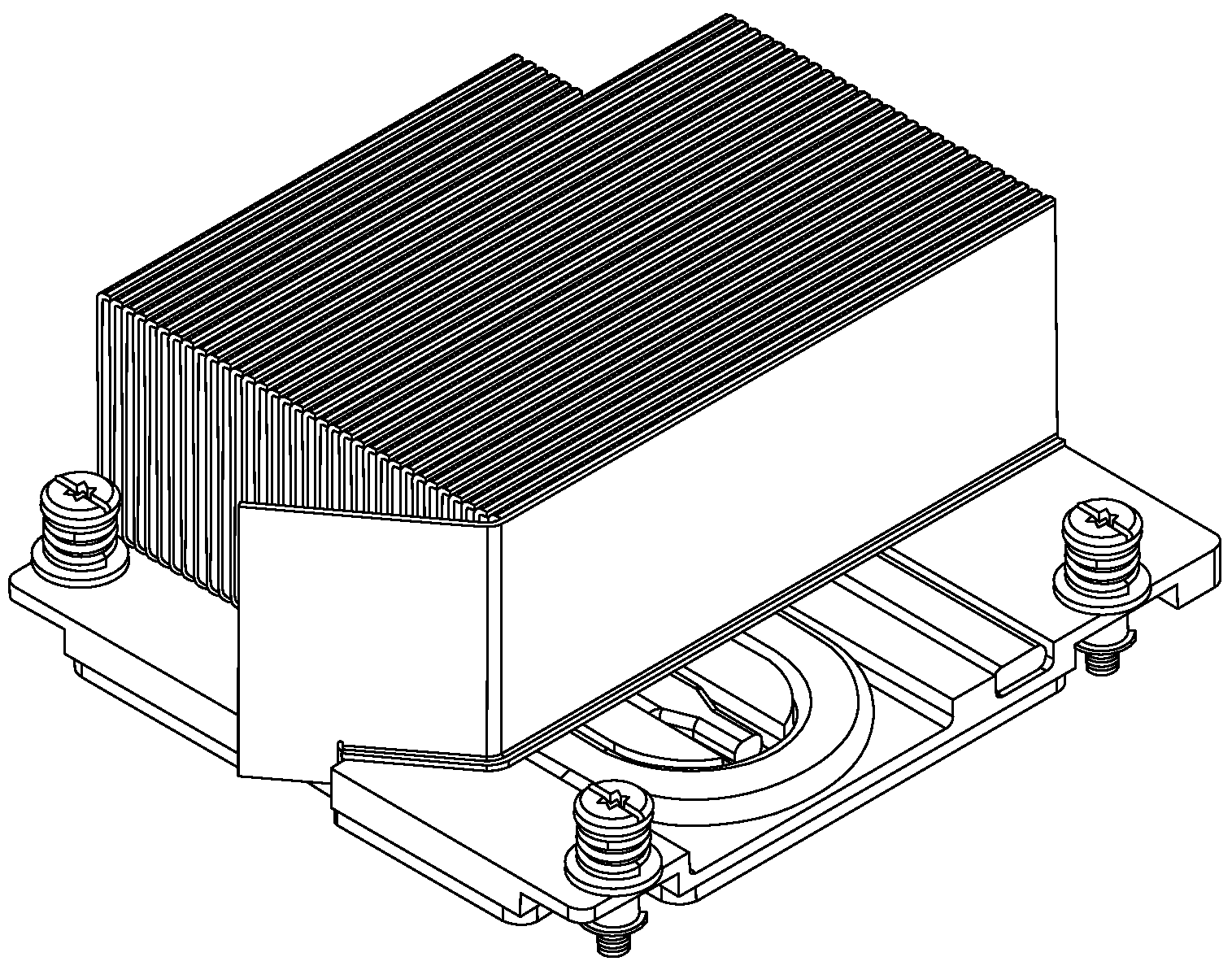
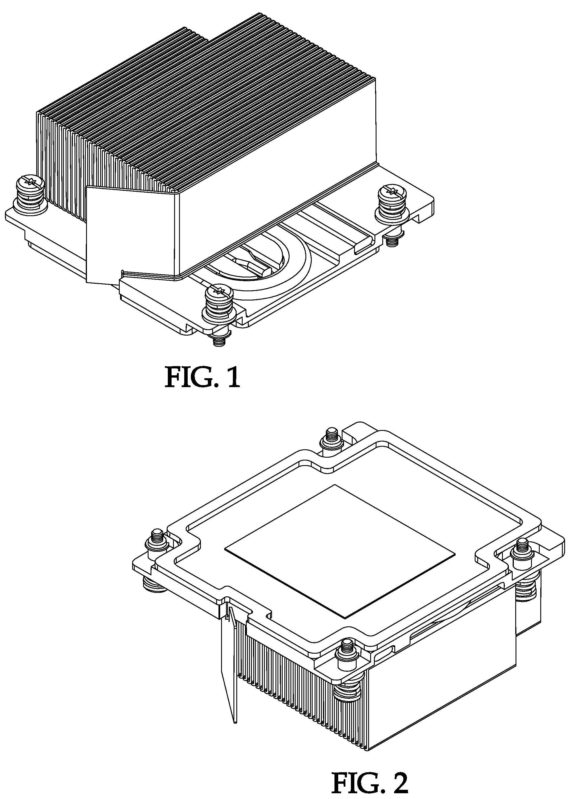
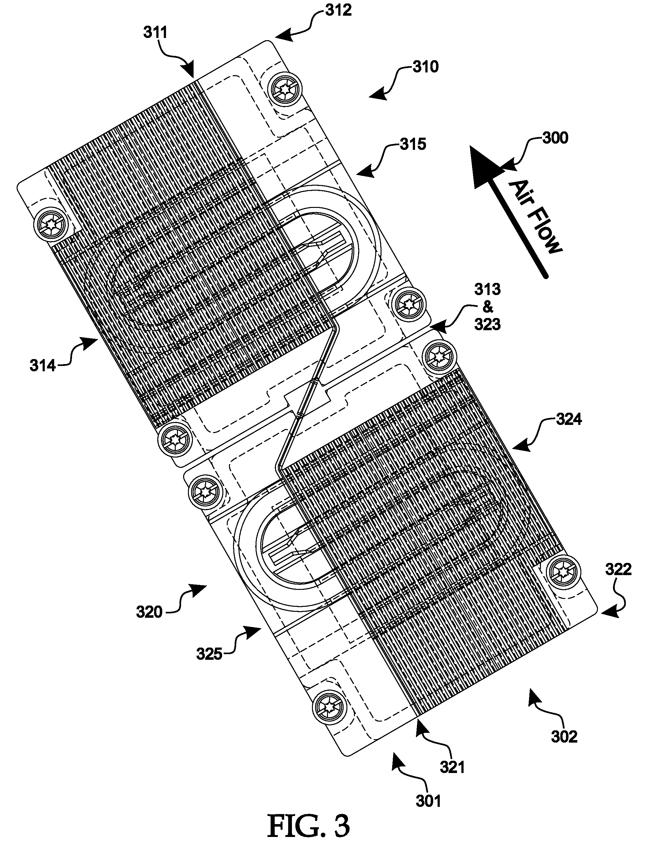
[0012]By dividing the air flowing across the processor region into two paths, each path primarily providing the cooling air flow of a single processor, each processor has the same cooling opportunity. Air passing across the forward processor will not preheat the air thus hampering the cooling of the rear processor. A divider extends from the front of the forward processor's heat sink to the back of the rear processor's heat sink, separating the area above the heat sinks into two separate channels. Air passing across the processors is channeled down one side of the divider or the other. Each heat sink has fins on only one side of the divider such that air flowing through either of the channels passes across the fins of only one of the two processors. As air will flow through the open channel more freely than through the channel, which comprises cooling fins, the channels need not evenly divide the physical space.

[0013]Heat pipes imbedded in the heat sink's base plate ensure the entir...


PUM


Abstract

A system for maintaining heat sink temperature uniformity in a system with pairs of substantially similar components mounted on a surface in close proximity and substantially aligned with an air flow, where the air flow is divided into a plurality of air flows by dividers radiating upward from the heat sink bases' top surfaces and containing cooling fins on the heat sink on only one side of the divider, where each airflow is diverted past the cooling fins of at least one of the heat sinks without significant pre-heating and through the cooling fins of at least one of the other heat sinks.

Description

CROSS-REFERENCE TO RELATED APPLICATIONS[0001]This application claims priority to an earlier filed U.S. Provisional Application entitled “BACK TO BACK HEAT SINK TEMPERATURE UNIFORMITY THROUGH FLOW DIVERSION”, filed on 15 Feb. 2006, Ser. No. 60 / 773,421, which provisional application is hereby incorporated by reference into the present application.BACKGROUND OF THE INVENTIONBACKGROUND OF THE INVENTION [0002]The main components of a typical blade server consist of a plurality of CPUs, memory and hard drives. Today's blade servers are extremely dense and, therefore, pose serious cooling challenges to dissipate the heat from high power density components such as, the CPU. In a typical blade server, air is used as a coolant to carry the heat dissipated from the high power density components. To compound the heat dissipation problem, some CPU architecture requires specific memory and processor spacing. These space constraints necessitate that multiple CPUs be arranged back-to-back, a non-id...

Claims


Application Information

Patent Timeline
Patent Type & Authority Applications(United States)
IPC IPC(8): H05K7/20
CPCH01L23/4006H01L23/427H01L23/467H01L2924/0002H01L2924/00
Inventor FRANZ, JOHNJOSHI, SHAILESH
Owner HEWLETT PACKARD DEV CO LP
Why Eureka
Try Eureka