Constant resolution continuous hybrid zoom system

a hybrid zoom and constant resolution technology, applied in the field of optoelectronic equipment, can solve the problems of increased size and complexity, increased cost, power consumption, weight limitation and image artifacts, etc., and achieve the effect of reducing the cost of optical zoom, and increasing the size and complexity

Active Publication Date: 2020-03-31
IMMERVISION INC
View PDF4 Cites 0 Cited by
  • Summary
  • Abstract
  • Description
  • Claims
  • Application Information

AI Technical Summary

Benefits of technology

[0011]At the minimum field of view setting, the processing unit or the sensor unit can simply perform a crop of the input image to create the output image because the constant magnification already produces almost a 1:1 ratio between the image sensor pixels and the output image pixels. With hybrid zoom settings other than the minimum field of view, there is an over sampling of the source image compared to the output image and residual positive distortion. The processing unit can then digitally compress the center of the image to reduce oversampling and lower the image resolution from the input resolution to the required output resolution. This compression by the image processing unit is progressively softer until the selected edge of the FoV, where the ratio become 1:1 by design of the distortion profile for the wide-angle lens.
[0012]In some embodiments of the present invention, a smart binning processing unit can be coupled with the image sensor or a smart binning hardware can be used to pre-compress the central part of the image before sending the image to the processing unit. A smart binning image sensor can perform 1×1, 2×2, 3×3, 1×2, 1×3, 2×3, or any other combination of pixel binnings required to lower the image resolution in selected areas of the image while always limiting the interpolation ratio between the source resolution and the output image resolution. This smart binning image sensor allows lowering of the data bandwidth or required compression by the processing unit, which is especially useful if the processing unit would instead require time and power to do the same task. This smart binning image sensor is also useful by lowering the transmitted image size, allowing savings on the quantity of useless information transmitted. Finally, it can allow an increase in the frame rate of the camera or the signal-to-noise ratio.

Problems solved by technology

However, the fact that multiple cameras are necessary implies tradeoffs with cost, power consumption, size limitations, weight limitations and image artifacts created by the fusion of images coming from different cameras.
However, having moving parts inside optics increase the size and the complexity.
For some applications, such as for miniature wide-angle lenses for consumer electronics, the size constraints are too strict to allow the movement of some optical elements to create an optical zoom.
This computational operation is not able to create extra information and is very limited in increasing the output image quality.

Method used


Image

  • Constant resolution continuous hybrid zoom system
  • Constant resolution continuous hybrid zoom system
  • Constant resolution continuous hybrid zoom system

Examples


Embodiment Construction

[0022]The words “a” and “an”, as used in the claims and in the corresponding portions of the specification, mean “at least one.”

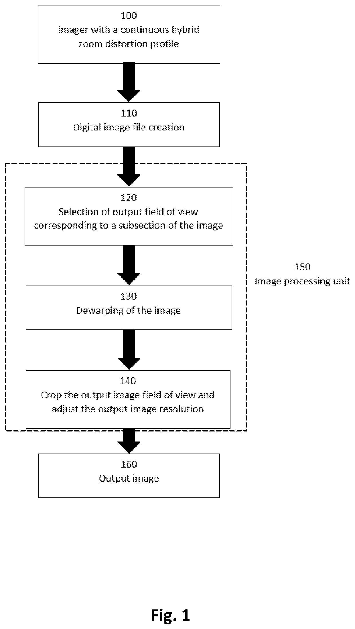
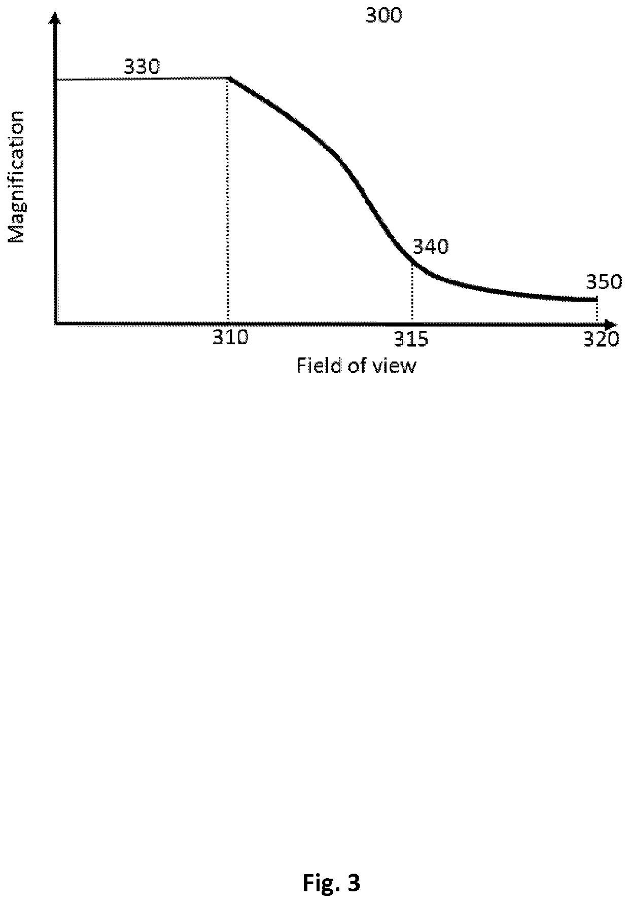
[0023]FIG. 1 shows a flow chart explaining the whole process for the continuous hybrid zoom system according to the present invention. The first step 100 is to use an imager having an imaging system with a distortion profile, as will be explained with reference to FIG. 3, and an image sensor. The imaging system generally includes a classical imaging lens with refractive elements either in plastic or in glass, but could also include other optical elements such as, but not limited to, diffractive elements, mirror, filters or the like. This imager 100 is used to capture a scene by converting the optical image from the imaging system to a digital image file at step 110 using its image sensor. The image sensor includes multiple image sensor pixels and can be of any type, such as, but not limited to, CCD, CMOS, NMOS or the like. The digital image file has a digit...


PUM


Abstract

The present invention relate to an optical apparatus to capture images of a wide-angle scene with a single camera having a continuous panomorph zoom distortion profile. When combined with a processing unit, the hybrid zoom system creates an output image with constant resolution while allowing continuous adjustment in the magnification and field of view of the image without interpolation like a digital zoom system or without any moving parts like an optical zoom system.

Description

CROSS-REFERENCE TO RELATED APPLICATIONS[0001]The present application claims the benefit of U.S. Provisional Patent Application No. 62 / 615,252, filed on Jan. 9, 2018, entitled “Constant Resolution Continuous Hybrid Zoom System,” currently pending, the entire contents of which are incorporated by reference herein.BACKGROUND OF THE INVENTION[0002]Embodiments of the present invention relate to an optoelectronic apparatus to capture images of a wide-angle scene with a single camera having a continuous panomorph zoom distortion profile. To create a continuous zoom for a human observer, instead of using pixel interpolation in order to maintain the amount of pixels in the final image or moving the optical element to change the magnification and reduce the lens field of view (“FoV”), or a combination of two or more cameras with different FoV, embodiments of the present invention use a distortion profile with a large constant magnification in a central area and a dropping magnification in the...

Claims


Application Information

Patent Timeline
Patent Type & Authority Patents(United States)
IPC IPC(8): G06T3/40H04N5/347H04N5/345H04N5/341H04N5/232G06T5/00
CPCG06T3/40H04N5/23296H04N5/347H04N5/3415H04N5/3454G06T5/006H04N5/23229H04N23/80H04N23/69H04N25/46H04N25/41H04N25/443
Inventor ROULET, PATRICEPARENT, JOCELYNDALLAIRE, XAVIERKONEN, PIERRENINI, PASCALE
Owner IMMERVISION INC
Why Eureka
Try Eureka