
Waveguide laser having reduced cross-sectional size and/or reduced optical axis distortion

a waveguide laser and cross-sectional technology, applied in the field of waveguide lasers, can solve the problems of large cross-sectional size of the conventional waveguide laser, and the inability to so as to reduce reduce the thermally induced distortion of the optical componen

Inactive Publication Date: 2007-08-16
VIDEOJET TECH INC
View PDF17 Cites 13 Cited by
  • Summary
  • Abstract
  • Description
  • Claims
  • Application Information

AI Technical Summary

Benefits of technology

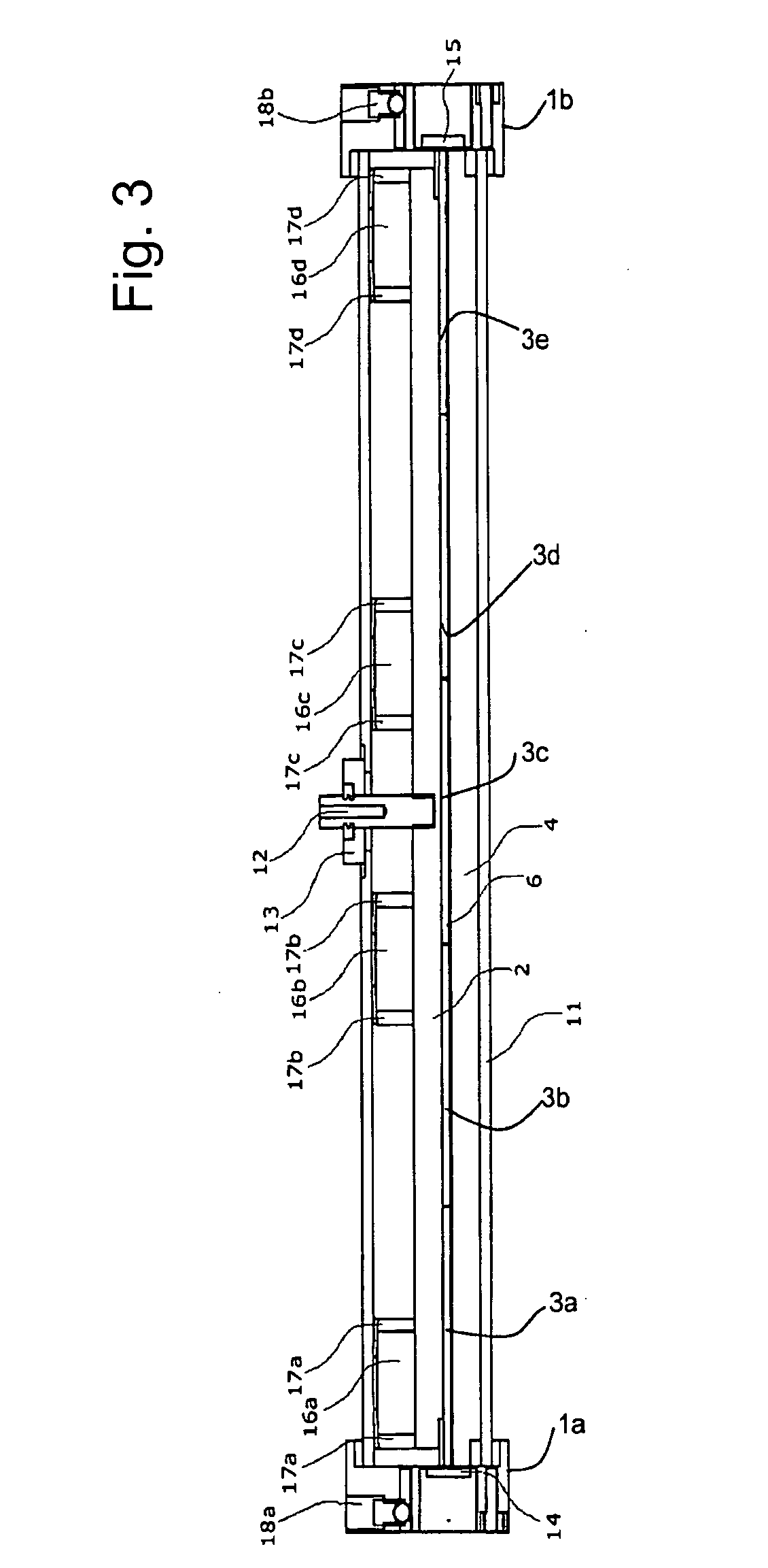
[0011] In certain example embodiments, a gas discharge laser is provided. The gas discharge laser may provide a vacuum vessel having an optical element connected to at least one of its ends. The vacuum vessel may comprise substantially adjacent first and second chambers. The first chamber may be a discharge chamber accommodating a discharge region. The second chamber may be a gas ballast chamber. The first and second chambers may be arranged so that heat generated in the discharge region flows away from the first and second chambers, thereby reducing thermally induced distortion of the optical component during laser operation.
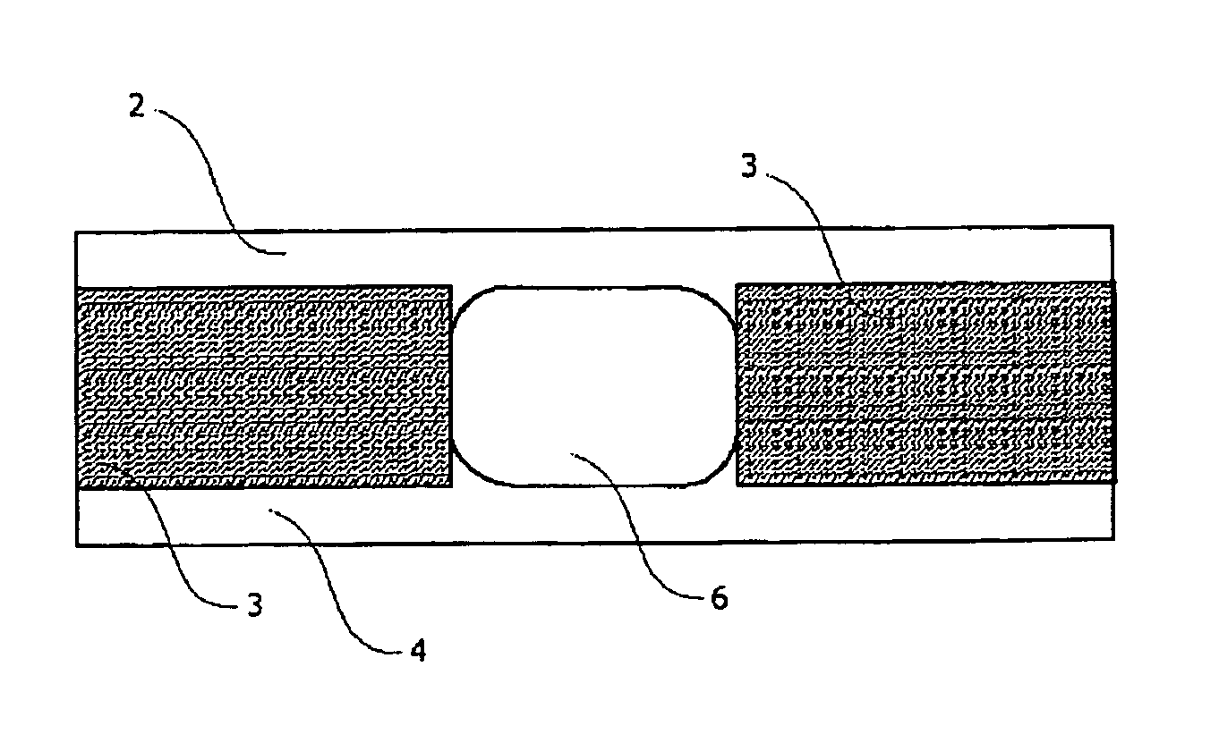
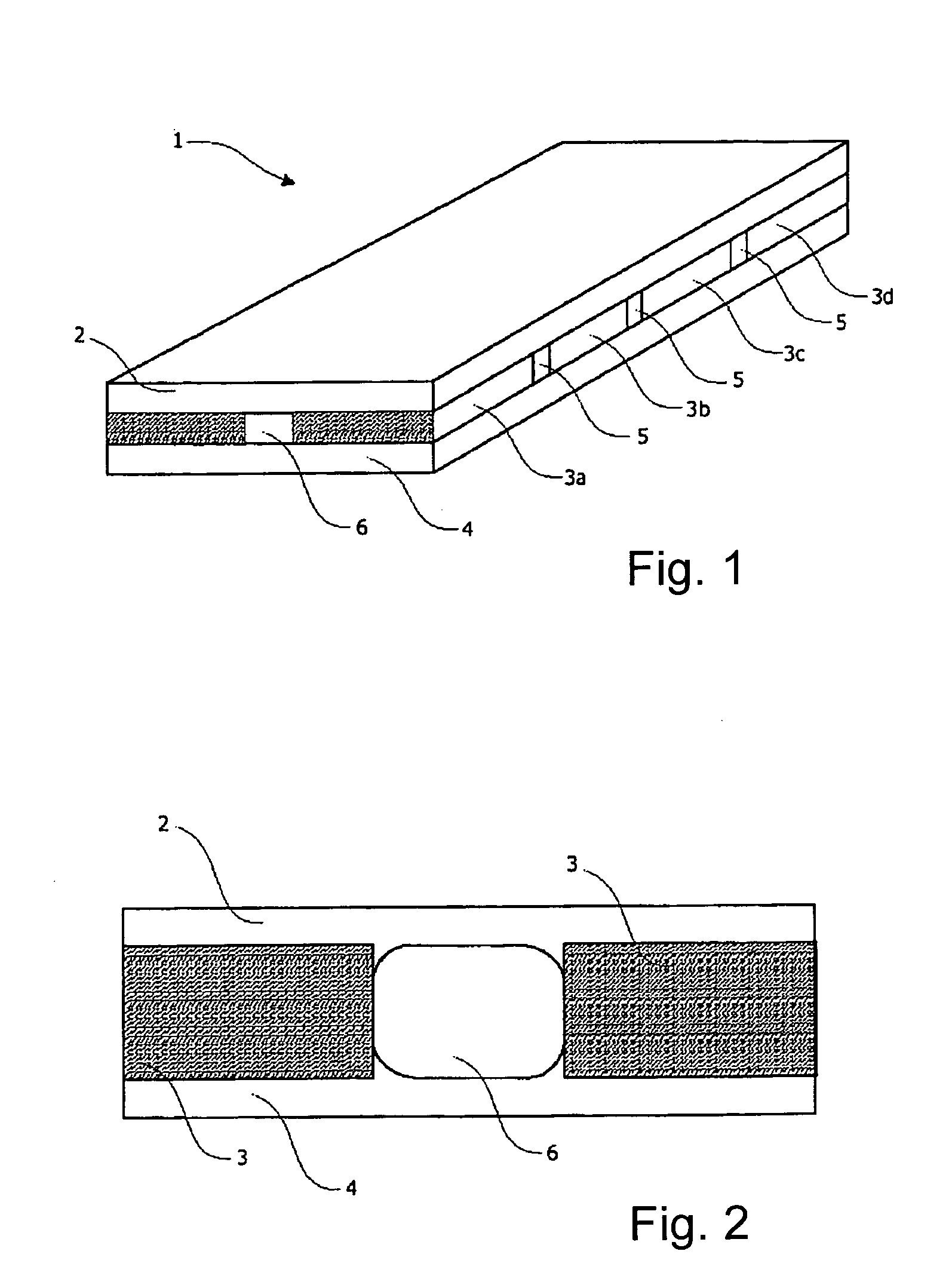
[0012] In still other example embodiments, a gas discharge laser is provided. This gas laser may comprise a top electrode for use with an RF discharge laser. The top electrode may include a metallic or substantially metallic layer deposited on an insulating carrier material. The top electrode may be generally elongated with substantially parallel sides, and with each said side including at least one cutout or gap in an RF coupling region so as to allow RF energy to couple through the top electrode without traversing the insulating carrier material. A vacuum vessel may have an optical element connected to at least one of its ends, with the vacuum vessel comprising substantially adjacent first and second chambers. The first chamber may be a discharge chamber accommodating a discharge region. The second chamber may be a gas ballast chamber. The first and second chambers may be arranged so that heat generated in the discharge region flows away from the first and second chambers, thereby reducing thermally induced distortion of the optical component during laser operation.

Problems solved by technology

Unfortunately, conventional waveguide lasers suffer from several disadvantages.
For example, CO2 lasers traditionally suffer from both a relatively large cross-sectional size and optical axis distortion because of differential heat removal from the laser's vacuum vessel.

Method used


Image

  • Waveguide laser having reduced cross-sectional size and/or reduced optical axis distortion
  • Waveguide laser having reduced cross-sectional size and/or reduced optical axis distortion
  • Waveguide laser having reduced cross-sectional size and/or reduced optical axis distortion

Examples


Embodiment Construction

[0021] In certain example embodiments of this invention, certain gas (e.g., CO2, N2, etc.) lasers may be constructed in stable, unstable, and / or waveguide resonator formats. The waveguide resonator format provides a relatively small waveguide cross-section (typically about 0.1 square inches, or other suitable dimension), and a higher discharge volume density than a stable or unstable resonator format. Existing design techniques create a large vacuum vessel around the waveguide, expanding the waveguide laser cross-section from about 0.1 square inches to typically about 2 square inches or the like. However, for certain applications (e.g., for product identification applications, such as, for example, marking food packaging and bottling, etc.), there is a need and / or desire to achieve a smaller cross-section. For example, it may be desirable in certain applications to achieve a cross-section of only about 1 square inch, or less, which translates into an almost 75% cross-sectional reduc...


PUM


Abstract

Certain example embodiments of this invention relate to waveguide lasers (e.g., RF-excited waveguide lasers). Certain example embodiments of this invention provide combined waveguide cover and non-coupled top electrodes, and / or heat load balancing vacuum vessels including multiple (e.g., two or more) chambers. In certain example embodiments, RF energy may couple through the combined waveguide cover and non-coupled top electrode without significantly traversing the insulating carrier material via one or more cutouts or gaps formed in the RF coupling region of the top (or even a bottom) electrode. In certain example embodiments, first and second chambers of the vacuum vessel may be arranged so that heat generated in the discharge region flows away from the first and second chambers, thereby reducing thermally induced distortion of the optical component during laser operation. These techniques may be used alone or in various combinations.

Description

CROSS-REFERENCE TO RELATED APPLICATION [0001] This application claims the benefit of U.S. provisional patent application No. 60 / 764,774, filed on Feb. 3, 2006, the entire contents of which are hereby incorporated herein by reference.FIELD OF THE INVENTION [0002] Certain example embodiments of this invention relate to waveguide lasers including but not limited to RF-excited waveguide lasers. More particularly, certain example embodiments of this invention relate to techniques for reducing the cross-sectional size and / or optical axis distortion of waveguide lasers by, for example, providing combined waveguide cover and non-coupled top electrodes and / or heat load balancing vacuum vessels including two chambers. BACKGROUND AND SUMMARY OF EXAMPLE EMBODIMENTS OF THE INVENTION [0003] A waveguide laser often includes mirrors, concave or flat, defining an optical resonator cavity coupled together with a waveguide defining an optical path between the mirrors. [0004] The waveguide typically in...

Claims


Application Information

Patent Timeline
Patent Type & Authority Applications(United States)
IPC IPC(8): H01S3/22H01S3/097
CPCH01S3/0315H01S3/036H01S3/0975H01S3/041H01S3/0971H01S3/0385
Inventor MONTY, NATHAN P.
Owner VIDEOJET TECH INC
Learn More