Optical devices for guiding illumination

Active Publication Date: 2007-08-16
VIAVI SOLUTIONS INC
View PDF35 Cites 113 Cited by
  • Summary
  • Abstract
  • Description
  • Claims
  • Application Information

AI Technical Summary

Benefits of technology

[0055]FIG. 42 is a perspective view of the device similar to FIG. 25 in which the beginning input portion of the body of the device is

Problems solved by technology

Although useful with their respective light sources in their particular applications, these light directing optical elements

Method used


Image

  • Optical devices for guiding illumination
  • Optical devices for guiding illumination
  • Optical devices for guiding illumination

Examples


first embodiment

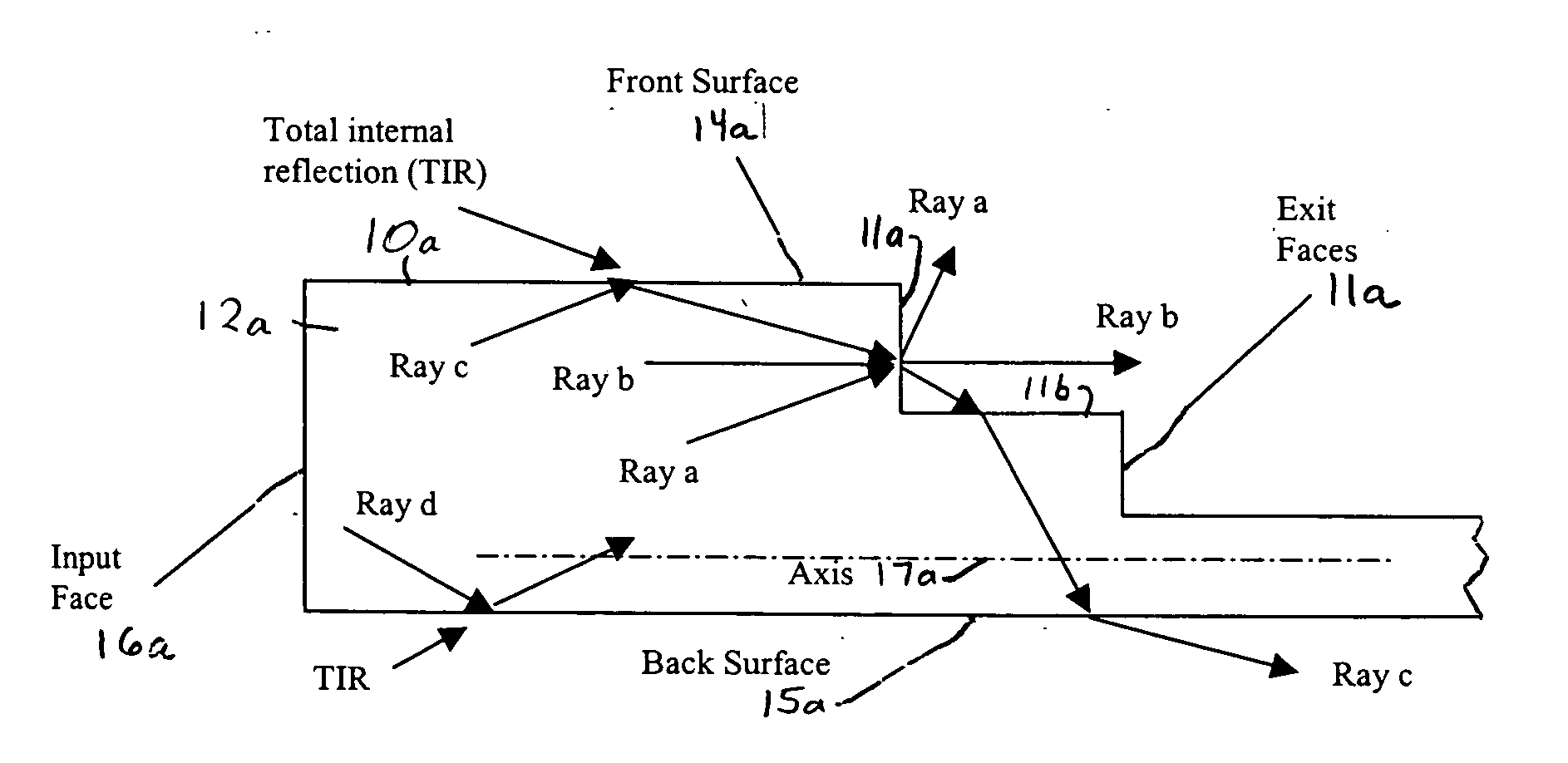
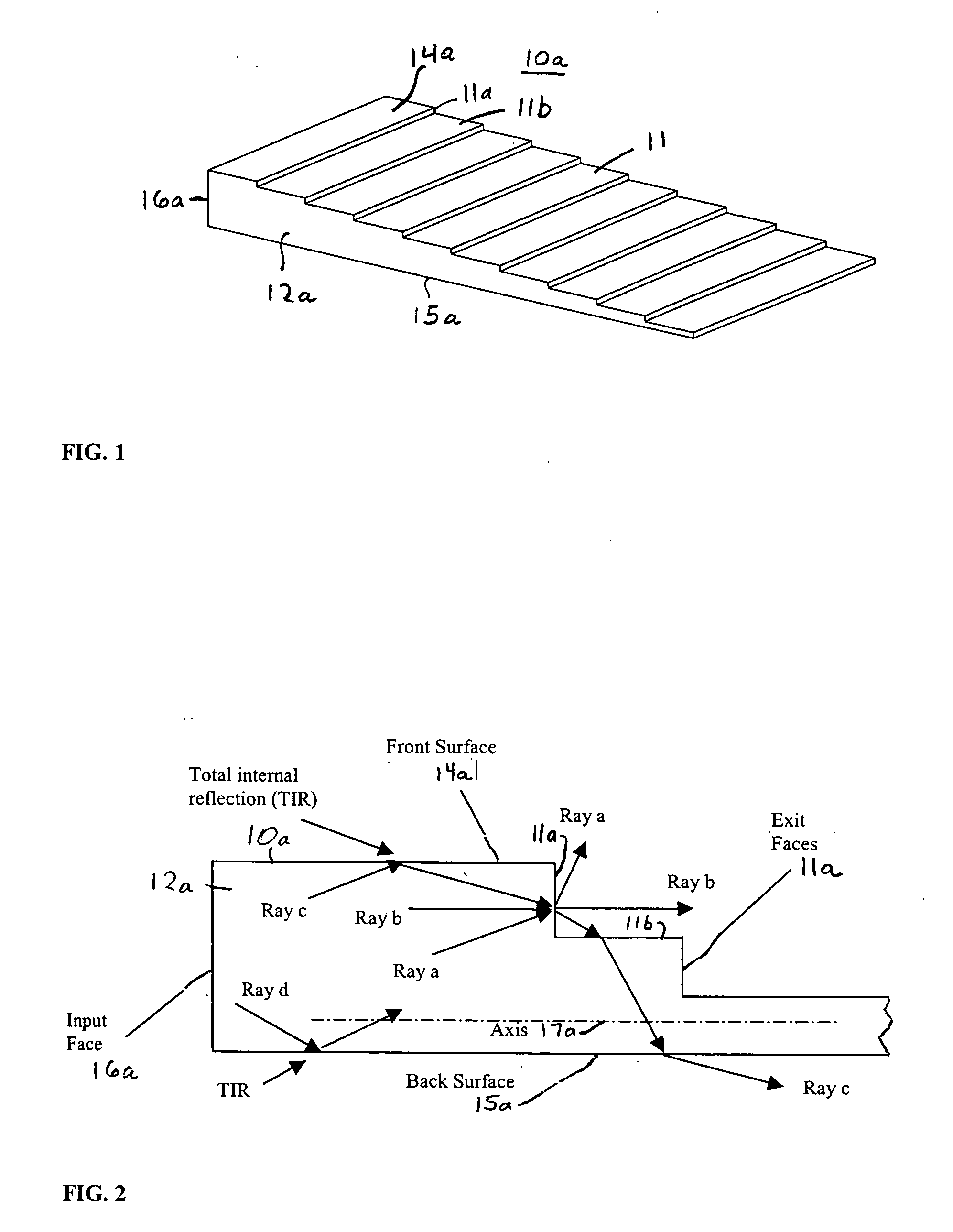
[0098] Now referring to FIG. 1, an optical device 10a of a first embodiment is shown having a body 12a of optical material with a series of steps providing a stair-case structure 11 along top surface 14a. Each of the steps is shown equally spaced. As will be shown by the theoretical discussion below, optical device 10a provides frontside output coupling, such that when light is inputted or injected into one end 16a of device 10a the light is distributed by the front exit face 11a of each of the steps, and a substantial portion of the light is internally reflected within body 12a until distributed from such front exit faces.

[0099] Optical device 10a is primarily provided to show the concept of the invention, and is considered least preferable of the embodiments described since features added to optical devices 10b-e can provide out-coupling of substantially all the light incident on a front-side while not increasing the numerical aperture of the light that does not exit the optical d...

second embodiment

Equation (34) is the criterion for Ray 2′ to exit optical device 10c and not reenter through the subsequent riser surface 20a. If α=1 then Equation (34) reverts to the expression in Equation (17) for second embodiment optical design 10b. The solutions to this relationship are plotted in FIG. 20. As the parameter α is increased, the upper angular limit moves down, narrowing the solution space. For the case of α=1.3, the riser angle must be less than 8 degrees for an exit face angle of 20 degrees. For example, an 8 degree riser angle for α=1.3 provides an effective thickness reduction, as described in Equation (29), of about 2.4 degrees.

[0129] The design constraint imposed by the extreme reflective-refractive ray interaction on the front-face 20b for optical device 10c will now be described. For this discussion, FIG. 21 shows the Ray 4′ interactions. The height of the ray Hray at the exit face 20b is given by the expression:

HRay≈(HEF−H)+LR*tan(Θ′Roy),   (35)

where once again this is...

fifth embodiment

[0158] Referring to FIG. 46A, optical device 10e of the present invention is shown having a structured backside surface that emits light from its top surface. Optical device 10e has a body 30 of optical material with ramp structures 32 and rising structures 36 that alternate with each other along the bottom surface 34 of the device. The ramp structures 32 and falling structures 36 extend along a dimension representing the axis 37 of the device, which is substantially parallel to the top surface 33 of the device, as best shown in FIG. 48. Each ramp structure 32 has a rising surface (or riser) 32a at an acute angle with respect to axis 37. Each falling structure has a falling surface at an acute angle with respect to the normal 37a of axis 37, and then a surface 36b substantially parallel to the top surface. The device's body gradually reduces in thickness as the ramp structures 32 alternate with the falling structures 36 extend along the device from end 38 to end 39. As will be shown...


PUM


Abstract

Optical devices for guiding illumination are provided each having a body of optical material with staircase or acutely angled ramp structures on its top surface for distributing light inputted from one end of the device from the front exit faces of such structures along certain angular orientations, while at least a substantial portion of the light is totally internally reflected within the body until distributed from such front exit faces. Optical devices are also provided each have a body of optical material having a bottom surface with acutely angled ramp structures and falling structures which alternate with each other, such that light is totally internally reflected within the device until reflected by such ramp structures along the bottom surface to exit the top surface of the device or transmitted through the ramp structures to an adjacent falling structure back into the device. Acutely angled ramp structures may be provided on both top and bottom surfaces of optical devices for distributing light along such top surface. Illumination apparatuses are also provided using such optical devices.

Description

FIELD OF THE INVENTION [0001] The present invention relates to optical illumination guiding devices, such as lightguides, and relates particularly to optical devices for guiding illumination having stair-case or acutely angled ramp structures along their top surface, and / or acutely angled ramp structures along their bottom surfaces, for distributing light from their top surfaces, in which light is at least substantially totally internally reflected within the devices until distributed out of the devices by such structures. The optical devices of the present invention guide light through the process of total internal reflection to be efficiently delivered accordingly to predefined spatial and angular distribution. The optical devices of the present invention are useful for a variety of illumination applications, such as architectural illumination, displays, backlighting, solid-state lighting, signage, or consumer products. The present invention also relates to illumination apparatuse...

Claims


Application Information

Patent Timeline
IPC IPC(8): G02B6/10
CPCG02B6/0028G02B6/0061G02B6/0048G02B6/0038G02B6/00G02B6/0001
Inventor CHAKMAKJIAN, STEPHEN H.SCHERTLER, DONALD J.SALES, TASSOMORRIS, G. MICHAEL
Owner VIAVI SOLUTIONS INC
Why Eureka
Try Eureka