
Tool setter for a grinding machine

a technology for grinding machines and tool sets, which is applied in the direction of metal-working holders, positioning devices, supports, etc., can solve the problems of prolonging the useful life of tools, affecting the use of tools, so as to improve the versatility of devices and improve the use effect of tools. , the effect of more tool edge shapes and angles

Active Publication Date: 2007-08-16
TORMEK
View PDF6 Cites 0 Cited by
  • Summary
  • Abstract
  • Description
  • Claims
  • Application Information

AI Technical Summary

Benefits of technology

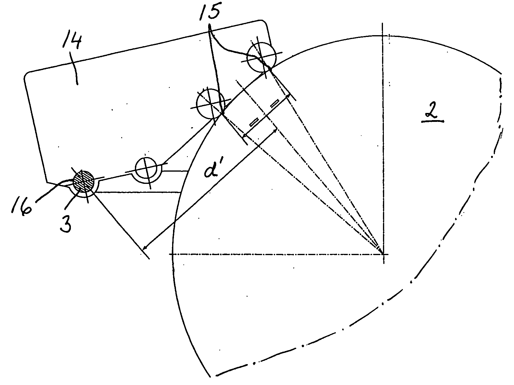
[0011]In order to improve the versatility of the device and allow more tool edge shapes and angles to be obtained, the plate may be provided with at least one further hole for optional connection to the support bar.
[0012]A replicated sharpening result is dependent on the use of the same protrusion of the tool from a jig utilized at grinding. For facilitating the setting of this protrusion, the plate is provided with a projection forming shoulders at different distances from an edge of the plate.
[0013]The plate may be provided with magnets for attachment of the device to a metal surface, for example the grinding machine, so as to prevent it from being lost.

Problems solved by technology

At re-sharpening of the tool by means of a jig very little steel is removed, and the wear is minimal, prolonging the useful life of a tool.
This is a rather awkward process, also with an inherent risk of then loosing a particular wooden spacer.
Further, the spacer can not be used with a grindstone with another diameter than the original one, if a replicated edge angle is desired.

Method used


Image

  • Tool setter for a grinding machine
  • Tool setter for a grinding machine
  • Tool setter for a grinding machine

Examples


Embodiment Construction

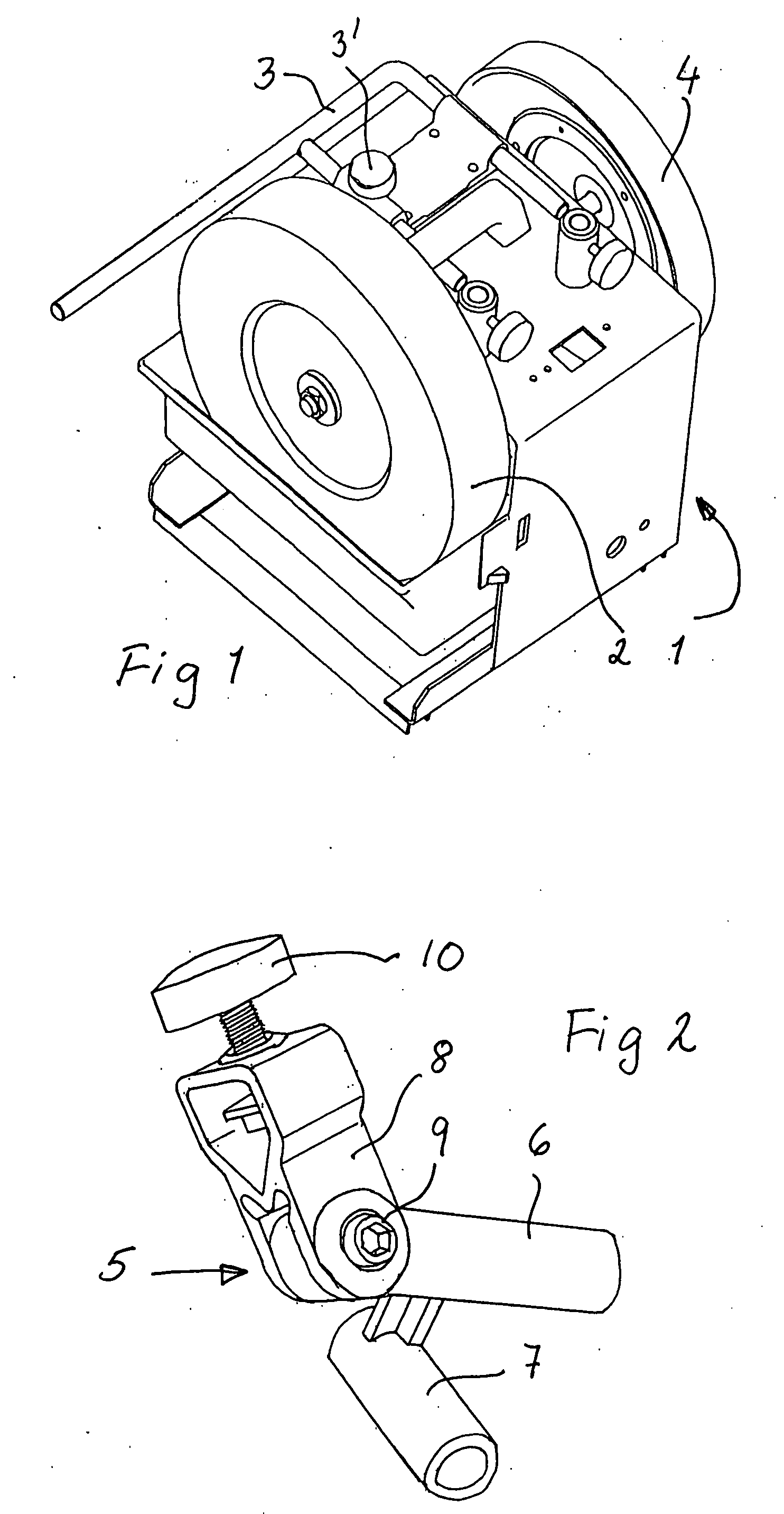
[0022]A conventional grinding machine 1 is shown in FIG. 1. The machine is provided with a circular grindstone 2 driven by an electric motor in the machine. The machine is provided with a cylindrical support bar 3. The purpose of the support bar 3 is to serve as a guiding means, as will appear below. The distance between the grindstone 2 and the support bar 3 parallel therewith may be adjusted by the slidable mounting of the support bar 3 to the grinding machine 1. The distance may be fixed by a set screw 3 on the machine.

[0023]The grinding machine 1 may also be provided with a honing wheel 4.

[0024]When edge tools, especially woodturning tools, such as chisels and gouges, most importantly spindle gouges, bowl gouges and plain or oval skew chisels, are to be sharpened by means of the grinding machine 1, use can be made of a jig 5 to be briefly described with reference to FIG. 2. The jig has a base member 6 with a support bar tube 7 attached perpendicularity thereto. The inner diamete...


PUM

PropertyMeasurementUnit
angleaaaaaaaaaa
diameteraaaaaaaaaa
distanceaaaaaaaaaa

Abstract

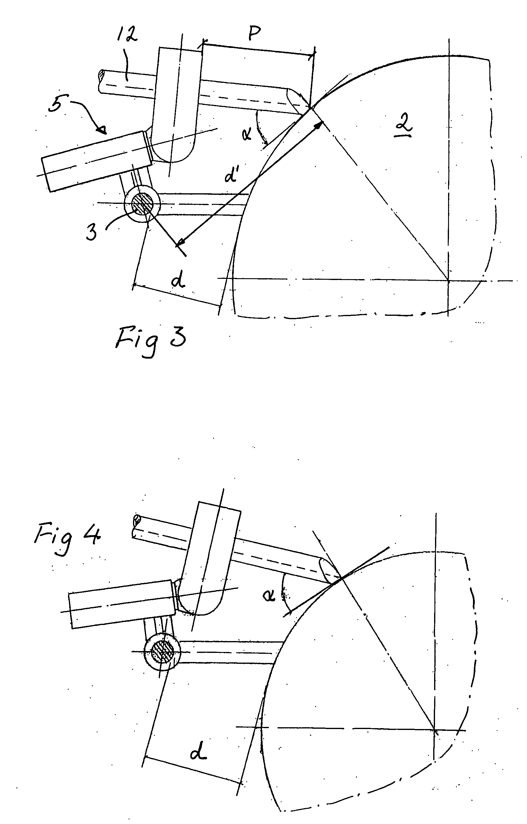
A device or tool setter has the purpose of setting the position of a support bar, adjustably connected to a grinding machine, in relation to a rotatable grindstone of the machine for obtaining a desired edge angle of a tool supported for grinding by the support bar. The device is provided with discs for defining two contact points with the grindstone and a hole for connection to the support bar.

Description

TECHNICAL FIELD[0001]The present invention relates to a device, hereinafter also referred to as a tool setter, for setting the position of a support bar, adjustably connected to a grinding machine, in relation to a rotatable grindstone of the machine for obtaining a desired edge angle of a tool supported for grinding by the support bar.BACKGROUND OF THE INVENTION[0002]Edge tools, for example for woodworking, especially woodturning tools, have to be sharp for obtaining optimum results. Sharpening can be performed by means of a rotating grindstone in a grinding machine. The sharpening is preferably carried out by means of a jig, in which the tool is attached and which is supported by a support bar of the machine. In this way an exact replication of the edge shape and edge angle of a previous sharpening can be obtained.[0003]Hereby, the shape of the edge is exactly the same after each re-sharpening, so that the tool always behaves in the same way at work. With a sharp edge the wood sur...

Claims


Application Information

Patent Timeline
Patent Type & Authority Applications(United States)
IPC IPC(8): B24B51/00B24B41/06
CPCB24B41/066B24B3/38B23Q3/10B24B3/34B24B3/36B27G23/00G01B3/56
Inventor JANSSON, TORGNY
Owner TORMEK
Learn More