Method of pretensioning power transmission chain,device for said method and power transmission apparatus

a technology of power transmission chain and pretensioning device, which is applied in the direction of metal chains, mechanical equipment, hoisting equipment, etc., can solve the problems of affecting the homogenization of chain length and chain pitch, imposing excessive tension load on the link plate and the pin member, and affecting the quality of the power transmission chain, etc., to achieve stability and effect of long-term

Inactive Publication Date: 2007-08-16
JTEKT CORP
View PDF0 Cites 3 Cited by
  • Summary
  • Abstract
  • Description
  • Claims
  • Application Information

AI Technical Summary

Benefits of technology

[0030]With the method and device for pretensioning the power transmission chain according to the invention, since excessive tension load is not imposed on the link plate and the pin member, the chain length or chain pitch is more uniform, whereby the quality is stabilized. With the power transmission apparatus of the invention, the power transmission chain is pretensioned by the pretensioning method, whereby the power transmission can be effected stably for the long term.

Problems solved by technology

However, in this case, since the distance between two rollers is long, and the chain needs to be rotated endlessly at high speed to shorten the working time, a large impact or vibration Occurs when the chain is rotated, likely imposing an excessive tension load on the link plate and the pin member.
Therefore, homogenization of the chain length and chain pitch is adversely affected, and the quality of the power transmission chain may not be stabilized.

Method used


Image

  • Method of pretensioning power transmission chain,device for said method and power transmission apparatus
  • Method of pretensioning power transmission chain,device for said method and power transmission apparatus
  • Method of pretensioning power transmission chain,device for said method and power transmission apparatus

Examples


Embodiment Construction

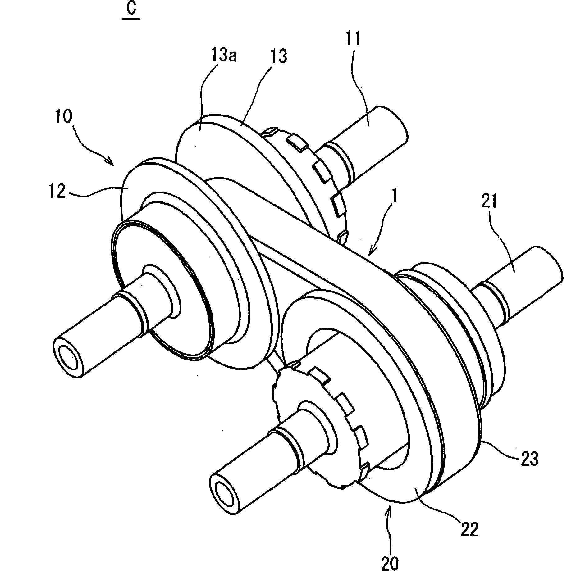
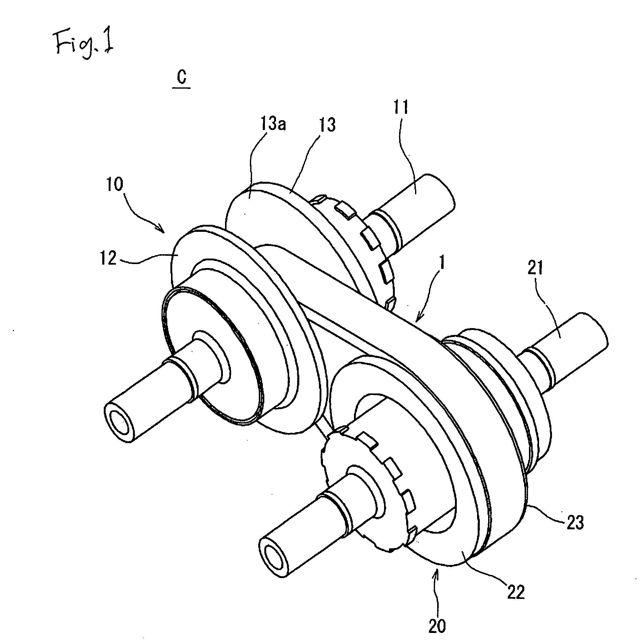
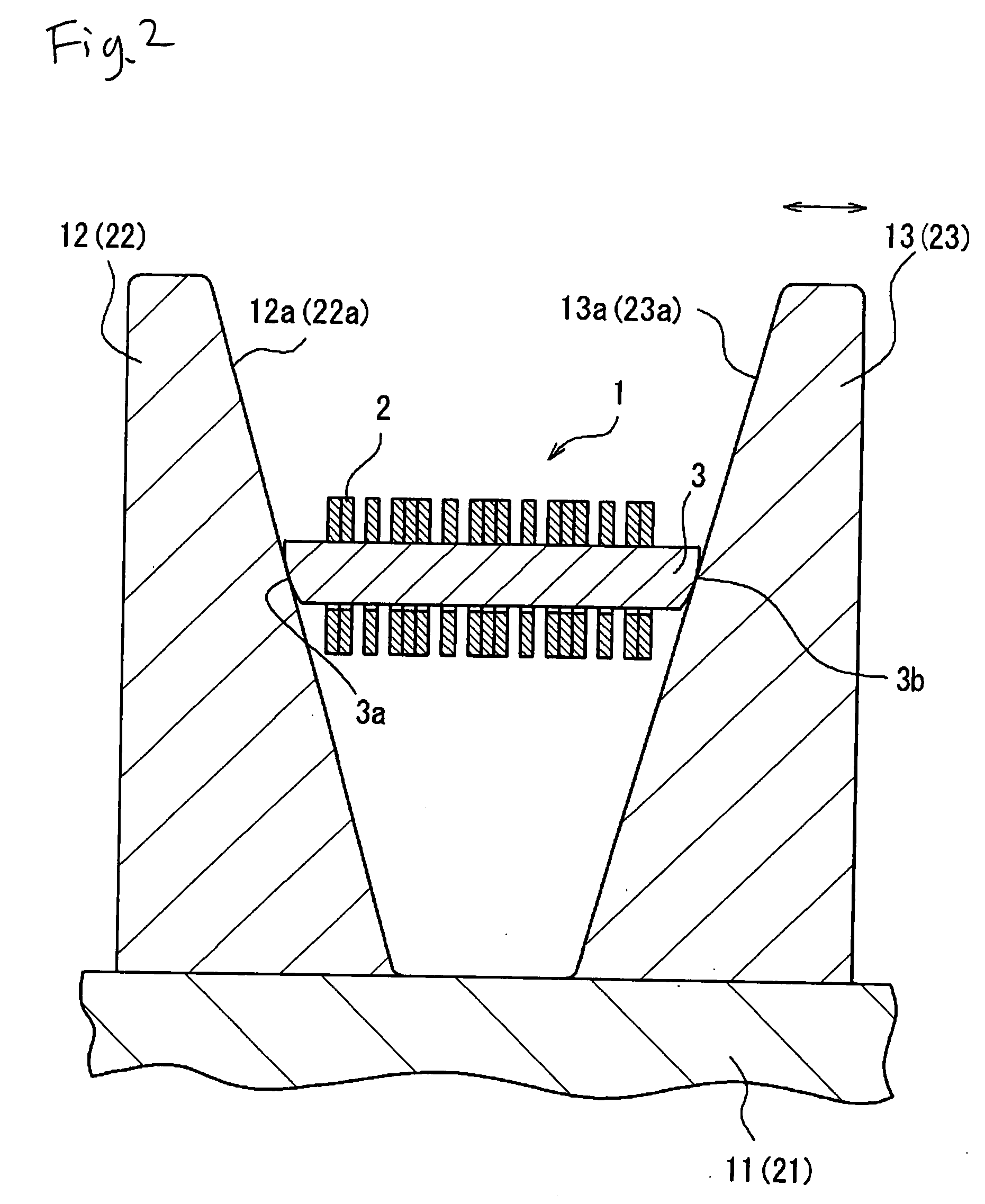
[0038]The embodiments of the present invention will be described below with reference to the accompanying drawings. FIGS. 1 and 2 show a chain type continuously variable transmission C (hereinafter simply referred to as a “continuously variable transmission”) in a power transmission apparatus according to the embodiment of the invention. FIGS. 3 and 4 show a power transmission chain 1 (hereinafter simply referred to as a “chain”) used for the continuosly variable transmission C. The continuously variable transmission C according to this embodiment is mounted on an automobile, for example, and comprises an input pulley 10 made of metal (structural steel) as the first pulley, an output pulley 20 made of metal (structural steel) as the second pulley, and the power transmission chain 1 looped over those pulleys.

[0039]The input pulley 10 is attached around an input shaft 11 connected on the engine side so as to be rotatable together, and comprises a fixed sheave 12 having a conical incli...


PUM

PropertyMeasurementUnit
bending angleaaaaaaaaaa
chain lengthaaaaaaaaaa
tensionaaaaaaaaaa

Abstract

An endless loop-like chain 1p consists of a plurality of link plates, laminated, that are linked to be freely bendable by pin members. The endless loop-like chain 1p is looped over each of the upper rollers and a lower roller to make up a polygon. If the chain is rotated endlessly while a tension load is imposed on the chain by each of the rollers, a pretensioned chain is obtained.

Description

BACKGROUND OF THE INVENTION[0001]The present invention relates to a power transmission apparatus of a chain type continuously variable transmission or the like that is used for the vehicle and so on, a method of pretensioning a power transmission chain for use in this power transmission apparatus, and a pretensioning device for this method.[0002]A continuously variable transmission (CVT) for the vehicle comprises an input pulley provided on the engine side, an output pulley provided on the driving wheel side, and an endless power transmission chain looped over both pulleys, for example. The power transmission chain is constituted by inserting a pin and a strip as the pin member through a pin hole provided in a link plate, in which a frictional force is generated by placing a conical sheave face of each pulley and a pin end face of the chain, for example, in some sliding contact in the peripheral direction of the sheave face, and a motive power is transmitted with this frictional for...

Claims


Application Information

Patent Timeline
Patent Type & Authority Applications(United States)
IPC IPC(8): F16H55/56F16H59/00
CPCB21L15/00F16G5/18B21L15/005
Inventor KAMAMOTO, SHIGEOKUSTER, JOELTADA, SEIJI
Owner JTEKT CORP
Why Eureka
Try Eureka