Method of making a surgical clamp

a technology of surgical retractor and clamping, which is applied in the field of surgical tools, can solve the problems of significant shrinkage during manufacturing of metal injection molding process, and achieve the effects of avoiding non-uniform shrinkage, increasing the dimensional tolerance of the cam member, and uniform thickness and volum

Inactive Publication Date: 2007-08-16
MINNESOTA SCI
View PDF25 Cites 5 Cited by
  • Summary
  • Abstract
  • Description
  • Claims
  • Application Information

AI Technical Summary

Benefits of technology

[0006] The present invention is a surgical clamp and clamping system using a handle, which, in one aspect, is unitarily formed with the wedge or cam member. The handle / cam is not machined from bar stock or from a casting, but rather is metal injection molded. The metal injection molding process includes a significant shrinkage during manufacture. In one aspect, the handle utilizes the benefits of the metal injection molding process in providing a shaped handle with a double offset, while avoiding non-uniform shrinkage by providing a design with largely uniform thicknesses and volumes. In another aspect, dimensional tolerances on the cam member are increased by having a separate, post-initial assembly manufacturing adjustment for the distance through which the camming action is applied on the other parts of the clamp design.

Problems solved by technology

The metal injection molding process includes a significant shrinkage during manufacture.

Method used


Image

  • Method of making a surgical clamp
  • Method of making a surgical clamp
  • Method of making a surgical clamp

Examples


Embodiment Construction

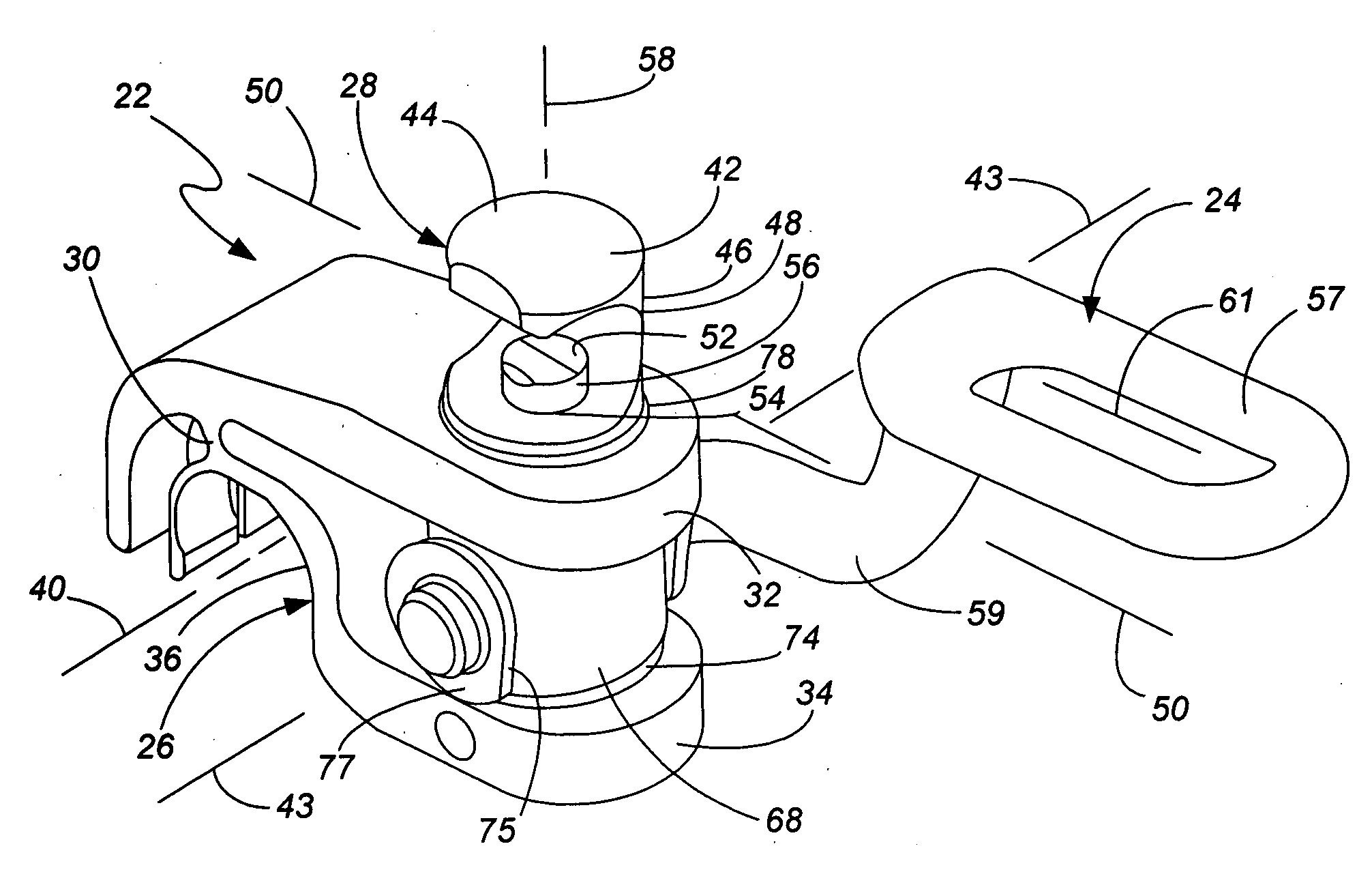
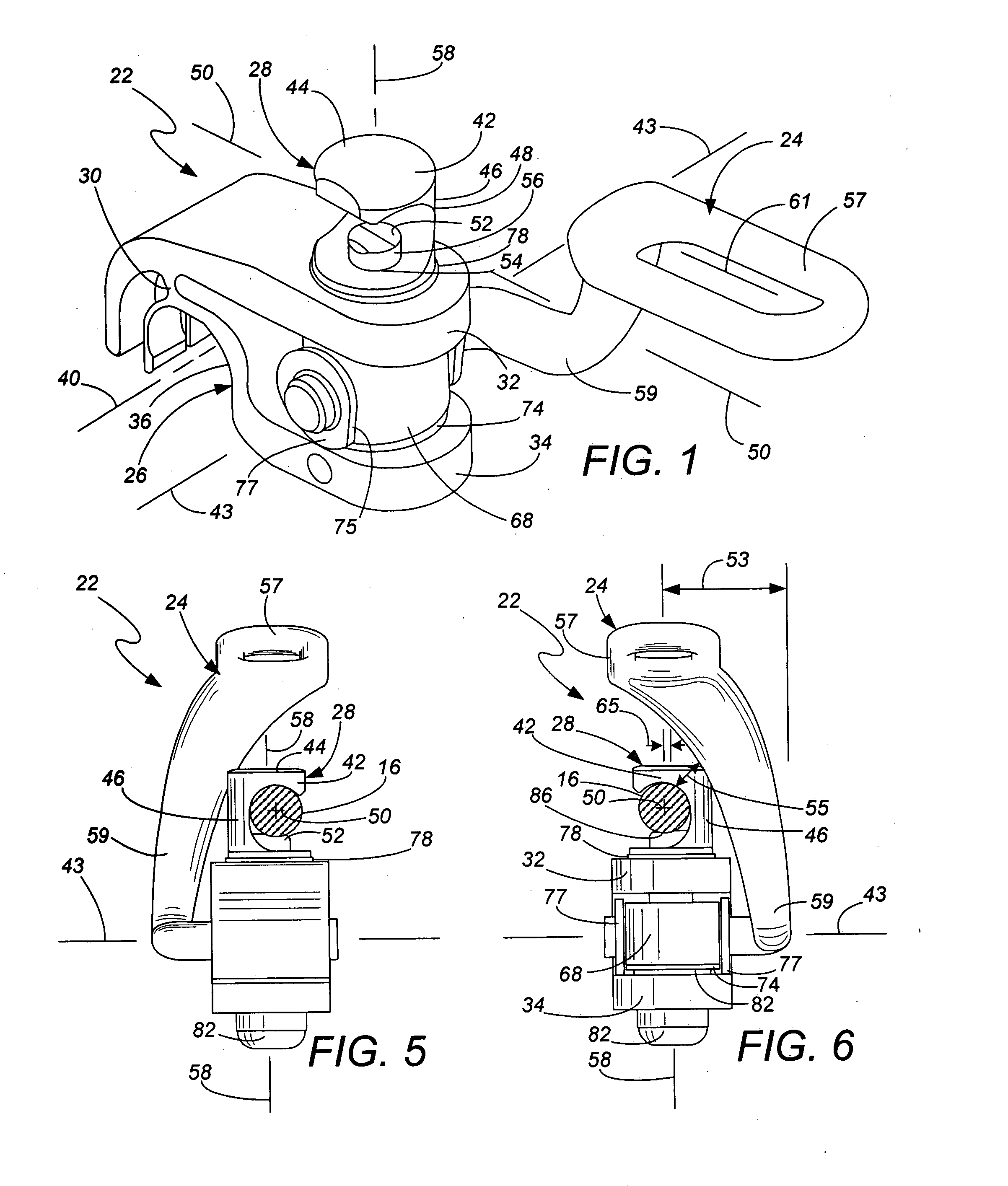
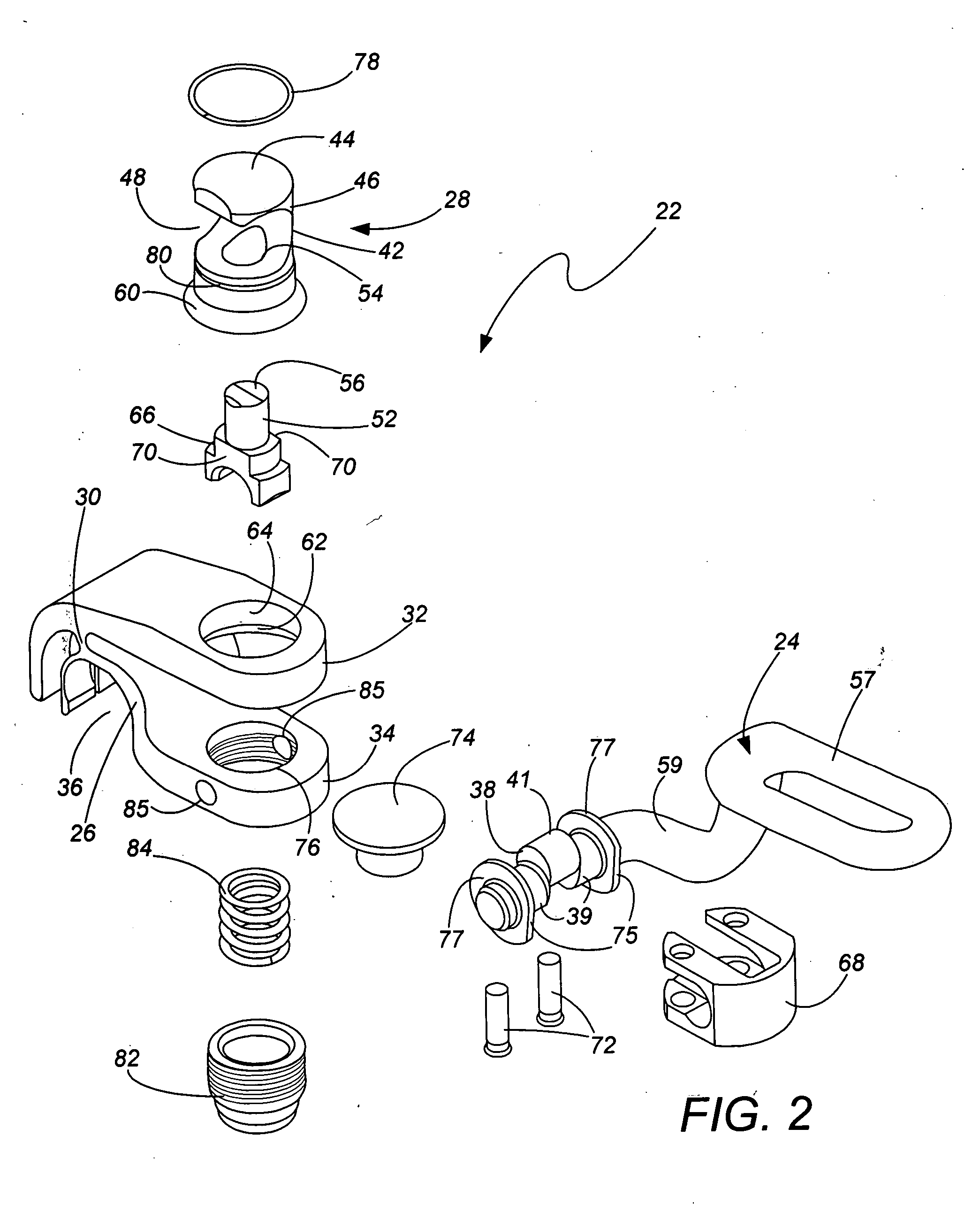
[0017] The method and apparatus of the present invention will be described with reference to a clamp member 22 as further disclosed in Application No. M1.12-4, incorporated by reference. The clamp 22 primarily includes a tightening handle 24, a first clamp member 26 (in the lower position as shown in FIGS. 1-8, it being recognized that orientation of the clamp 22 may depend upon use) and a second clamp member 28 (in the upper position as shown in FIGS. 1-8). For ease of description, the first or lower clamp member 26 will be called a “frame” clamp and the second or upper clamp member 28 will be called a “shaft” clamp, recognizing that the first clamp 26 may attach to a rod other than the support frame 18 and the second clamp 28 may attach to a rod other than a retractor shaft 16.

[0018] The frame clamp 26 may be a fulcrum clamp as generally disclosed in U.S. Pat. No. 5,727,899 and in application Ser. Nos. 10 / 664,195 filed Sep. 17, 2003 and 11 / 330,625 filed Jan. 12, 2006, all incorpo...


PUM


Abstract

A surgical clamp includes a support frame clamp member, a retraction shaft clamp member and a handle linked to the support frame clamp member and the retraction shaft clamp member for moving the clamp members between loosened and tightened positions. The handle includes a cam, and the handle / cam is unitarily formed by metal injection molding. The handle includes relatively uniform thickness throughout to better accept the shrinkage induced by the metal injection molding process. The base used for a bottom position of the cam is adjustable and spring loaded, to better support a wider range of manufacturing tolerances on the cam as well as the other components of the clamp without over stressing the metal injection molded handle during use. The handle includes a gripping portion with a planar portion inducing alignment of the clamping force as desired for best operation of the clamp.

Description

CROSS-REFERENCE TO RELATED APPLICATION(S) [0001] None. BACKGROUND OF THE INVENTION [0002] The present invention relates to the field of surgical tools, and particularly to the design and manufacture of surgical retractor systems. Surgical retractor systems are used during surgery to bias and hold tissue in a desired position. As one example, some surgical procedures require anterior access to the spine, through the patient's abdomen. Tissue such as skin, muscle, fatty tissue and interior organs needs to be held retracted to the side so the surgeon can obtain better access to the vertebrae structures of primary interest. [0003] Surgical retraction may be performed by one or more aides using handheld tools, with the most basic retractor apparatus being a tongue depressor. More commonly now in sophisticated operating rooms during abdominal or chest surgery, a surgical retractor system or assembly is used. The retractor assembly may, for instance, include a ring or support frame which i...

Claims


Application Information

Patent Timeline
Patent Type & Authority Applications(United States)
IPC IPC(8): A61B1/32
CPCA61B17/02A61B2017/00526A61B19/26A61B90/50
Inventor SHARRATT, TODD W.BERG, CHRISTOPHER LEEJACOBSON, STEVEN KARLRODBY, KEVIN
Owner MINNESOTA SCI
Why Eureka
Try Eureka