Compressive load sensor by capacitive measurement

Inactive Publication Date: 2007-08-23
DAVIE COFFEY TECH L L C
View PDF0 Cites 52 Cited by
  • Summary
  • Abstract
  • Description
  • Claims
  • Application Information

AI Technical Summary

Benefits of technology

[0012] A gasket sensor is provided to effectively measure parameters for optimum installation and early detection of gasket or conne

Problems solved by technology

Gasket applications include those required to contain liquids, gasses or solids where leakage could lead to emissions with detrimental effect to safety or the environment.
While an improvement over uncontrolled torqueing dependent on the skill and experience of the operator, perhaps even with a torque wrench, the bolt tension measurement approach contains many factors such as friction and lack of flange parallelism resulting in incorrect installation.
The approach does not address gasket sealing without tensioning bolts.
Similar problems exist in connections between members not carrying a gasket.
While these gasket sensors may work well within their intended applications, such additional elements and measurement complexities in addition to overall temperature limits and sensor fragility limit application to specific carefully designed uses.
Unfort

Method used


Image

  • Compressive load sensor by capacitive measurement
  • Compressive load sensor by capacitive measurement
  • Compressive load sensor by capacitive measurement

Examples


Embodiment Construction

[0045] In the description that follows, like parts are marked throughout the specification and drawings with the same reference numerals. The drawing figures might not be to scale and certain components can be shown in generalized or schematic form and identified by commercial designations in the interest of clarity and conciseness.

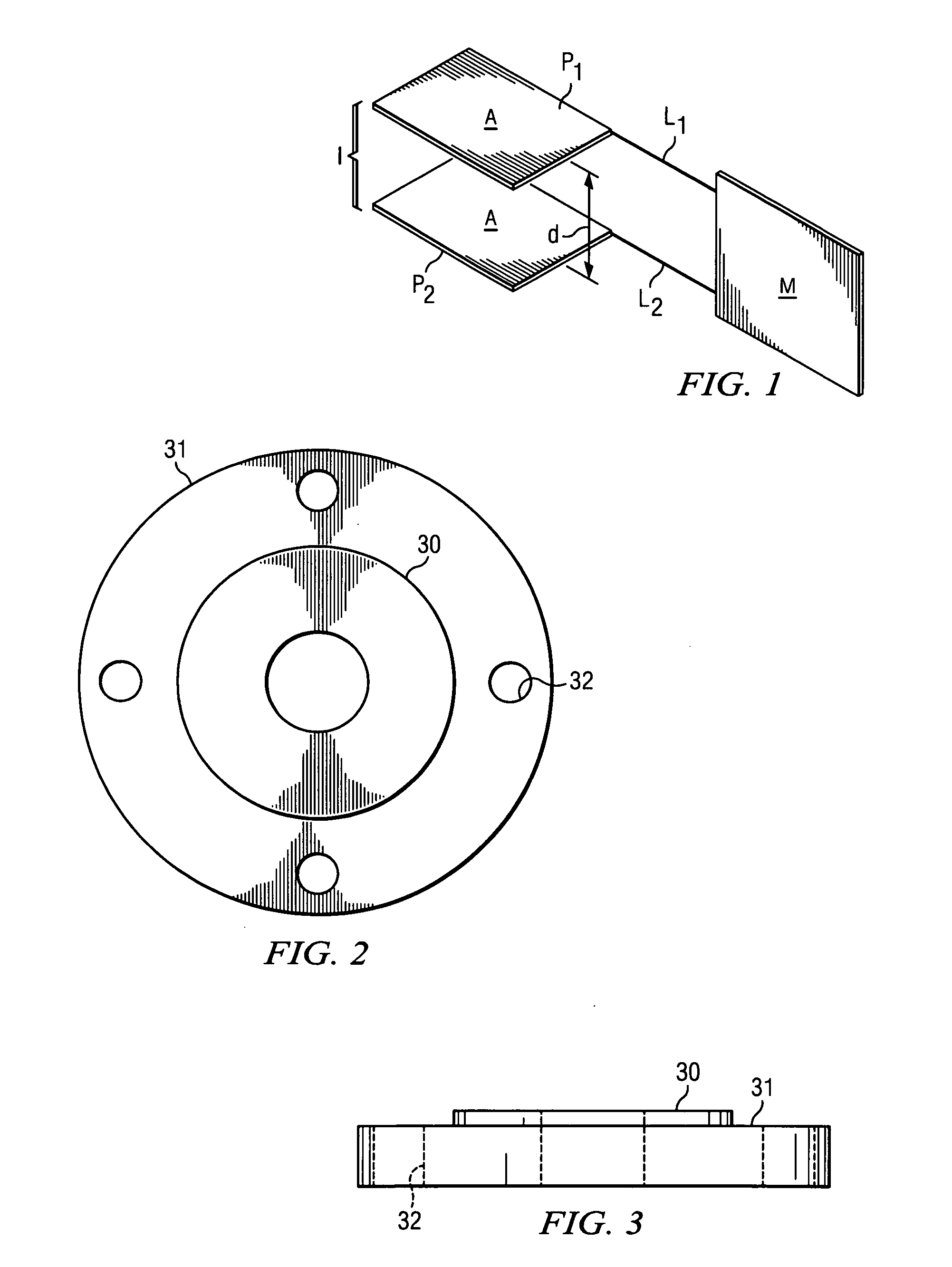
[0046]FIG. 1 is a schematic illustration of a parallel plate capacitor C that provides the basis for a capacitive load sensor in accordance with an exemplary embodiment of the present invention. Capacitor C includes two parallel plates P1 and P2 of equal area “A” formed of a metallic conductor with a dielectric material I between the plates. Dielectric material I has a dielectric constant “K,” whereas the dielectric constant for air is 1.0, such that the ratio of the capacitance of capacitor C to a capacitor with identical spacing and area using air as an insulator is “K.”

[0047] The parallel plates P1 and P2 area are shown connected via leads L1 and L2 t...


PUM


Abstract

A thin, flat capacitive load sensor, such as of layered sandwich construction, having a variety of shapes, so as to provide a seal between two or more opposing surfaces. The load sensor includes a thin first and second insulating outer layer between which an inner layer is secured. The inner layer can be formed of dielectric material of a known dielectric constant, with at least one thin electrical conductor to accommodate load sensing disposed against a first face, and another thin electrical conductor to accommodate load sensing disposed against a second face. Electrical conductors connect the thin conductive areas on the first and second faces to the distal end of a tab extending beyond the load or connection measurement area. The distal end of the tab accommodates a connection with electrical measurement apparatus. As the inner layer is compressed, the spacing between the electrically conductive areas on the opposing faces is decreased such that compressive forces can be measured as a function of the changes in capacitance of the sensor. In this manner, proper compression can be achieved by monitoring capacitance during installation. Follow-up sampling or continuous measurement of sensor compression provides early detection prior to failure to allow corrective action.

Description

RELATED APPLICATIONS [0001] This application claims priority to Ser. No. 10 / 191,155, filed Jul. 9, 2002, which claims priority to 60 / 311,156, filed Aug. 10, 2001, both of which are commonly owned and which are hereby incorporated by reference for all purposes.FIELD OF THE INVENTION [0002] The present invention pertains to the field of gasket condition monitoring, and more particularly to a system and method for gasket condition monitoring that utilizes capacitive sensors to determine the amount of compression on gasket material. BACKGROUND OF THE INVENTION [0003] Gaskets are used in many industrial and consumer applications to provide a conformable seal between mating surfaces. The effectiveness of the seal achieved is a function of the proper selection of gasket material for surfaces being sealed and contents to be contained within the vessel or piping being sealed. Proper installation of the gasket, for instance by compression of the material, is necessary for a lasting seal to be...

Claims


Application Information

Patent Timeline
IPC IPC(8): G01B7/16
CPCG01L5/243G01N2203/0617G01N2203/0278G01M13/005
Inventor COFFEY, E. MICHAELDAVIE, NEIL R.
Owner DAVIE COFFEY TECH L L C
Why Eureka
Try Eureka