Variable attenuation power damper

a damper and variable technology, applied in the direction of shock absorbers, springs/dampers, vibration suppression adjustments, etc., can solve the problems of low response, increase in parts, complex structure, etc., and achieve the effect of reducing the number of parts and assembly steps, enhancing the response in high-frequency input time to the damper, and expanding the adjustable width of the attenuation power

Inactive Publication Date: 2007-08-23
HONDA MOTOR CO LTD
View PDF4 Cites 48 Cited by
  • Summary
  • Abstract
  • Description
  • Claims
  • Application Information

AI Technical Summary

Benefits of technology

[0039] According to the constitution in the third aspect, the orifices are provided in the piston which is fitted slidably into the cylinder filled with the magnetic viscous fluid or the magnetic fluid, and the attenuation power of the damper can be controlled arbitrarily by deforming the valve plates provided in the piston by the magnetic fields generated by the coils and changing the opening of the orifices. In this case, by changing the viscosity of the magnetic viscous fluid or the magnetic fluid in the orifices by the magnetic fields which the coils generate, the attenuation power of the damper can be controlled arbitrarily. Thus, by combining the attenuation power generated by the orifice and the valve plate and the attenuation power generated by the magnetic viscous fluid or the magnetic fluid, the large attenuation power is generated, so that the adjustable width of the attenuation power can be expanded.
[0040] Further, according to the constitution in the forth aspect, the first valve plate is deformed by the corresponding first coil, and the second valve plate is deformed by the corresponding second coil. Therefore, compared with the case where these first and second valve plates are deformed by a common coil, the time interval for which the first and second coils are excited and demagnetized can be extended twice. Hereby, the influence of the inductance of the first and second coils can be suppressed to a minimum thereby to accelerate rising of the electric current, and response in high-frequency input time to the damper can be heightened.
[0041] Further, according to the constitution in the fifth aspect, the piston body of the piston is formed of one member from one end in its axial direction to the other end. Therefore, phase-matching of the fluid passages required in case that the piston body is formed of plural members is unnecessary, so that the number of parts and the number of assembly steps can be reduced.
[0042] Further, according to the constitution in the sixth aspect, the piston rod is inserted from one end in the axial direction of the piston and located on this side of the other end in. the axial direction thereof. Therefore, it is possible to suppress reduction of the volume of the piston functioning as a yoke by the piston rod to a minimum, and it is possible to heighten the absorption power of the first and second valve plates without increasing the electric current to be supplied to the first and second coils.
[0043] Further, according to the constitution in the seventh aspect, the first attenuation power control mechanism which changes the opening of the first orifice provided in the movable piston that is slidably fitted into the cylinder filled with the viscous fluid includes the first valve plate made of magnetic alloy and the first coil which generates the magnetic field, and the second attenuation power control mechanism which changes the opening of the second orifice provided in the fixed piston that is fixed between the cylinder and the reservoir room includes the second valve plate made of magnetic alloy and the second coil which generates the magnetic field, whereby the first and second valve plates are deformed by the magnetic fields generated by the first and second coils thereby to change the opening of the first and second orifices, and the attenuation power of the damper can be arbitrarily controlled. In this case, the first valve plate is deformed by the corresponding first coil, and the second valve plate is deformed by the corresponding second coil, whereby a time interval in which the first and second coils are excited and demagnetized can be prolonged twice, compared with the case where these first and second valve plates are deformed by a common coil. Hereby, the influence of the inductance of the first and second coils can be suppressed to a minimum thereby to accelerate rising of the electric current, and response in high-frequency input to the damper can be heightened.

Problems solved by technology

Since it is necessary for the variable attenuation power damper described in the above Patent Document 1 to arrange in the piston the spool valve which is operated by the solenoid, the number of parts increases and the structure becomes complicated.
In addition, since time lag exists after the solenoid is energized till the opening of the spool valve changes, there is a problem of low response.
However, when the frequency of load inputted in the piston becomes high, the coil must repeat excitation and demagnetization at short time intervals.
Therefore, rising of electric current in excitation time is delayed due to an influence of inductance of the coil, with the result that there is possibility that the response lowers.
However, since the attenuation power of the damper is adjusted by the opening of the orifice, it is difficult to sufficiently expand the adjustable width of the attenuation power by heightening the maximum attenuation power of the damper.

Method used


Image

  • Variable attenuation power damper
  • Variable attenuation power damper
  • Variable attenuation power damper

Examples


first embodiment

[0055] An embodiment of the invention will be described below with reference to attached drawings.

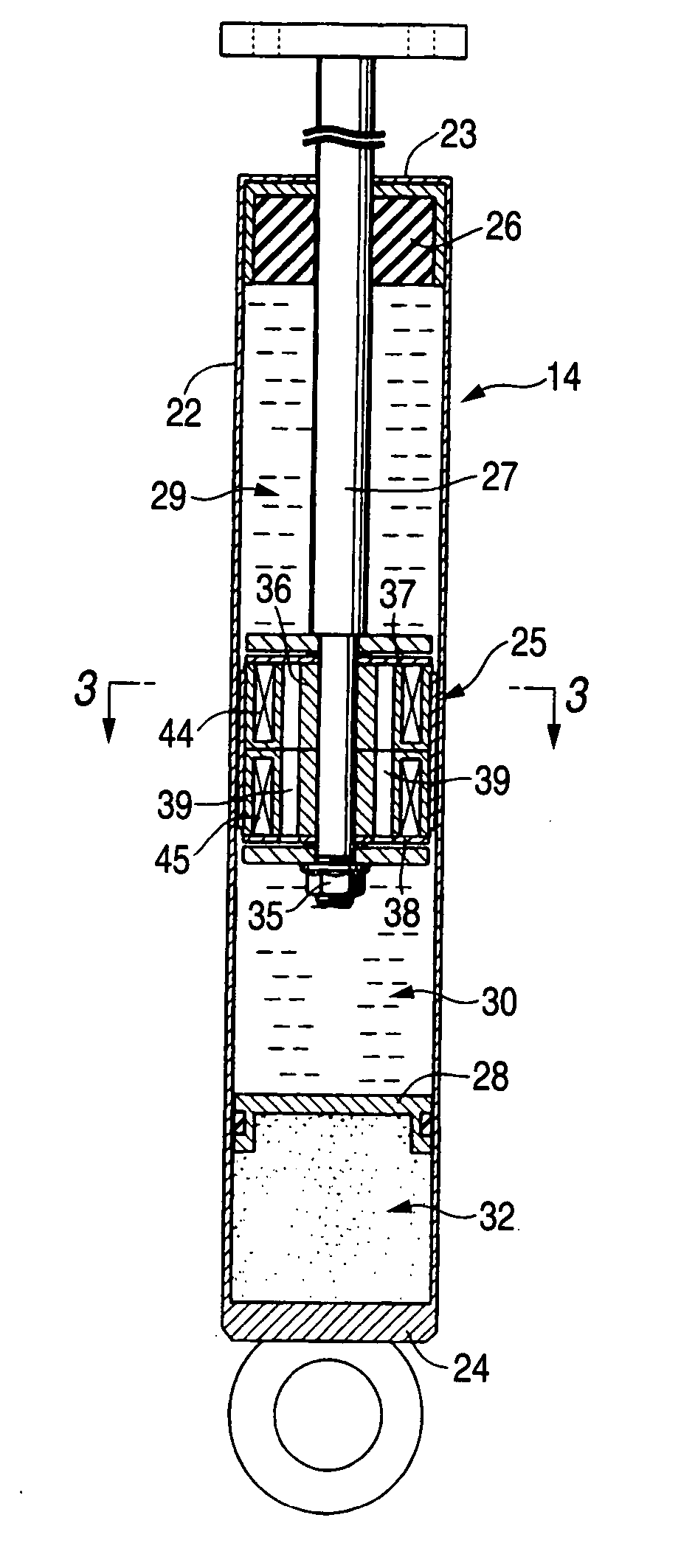
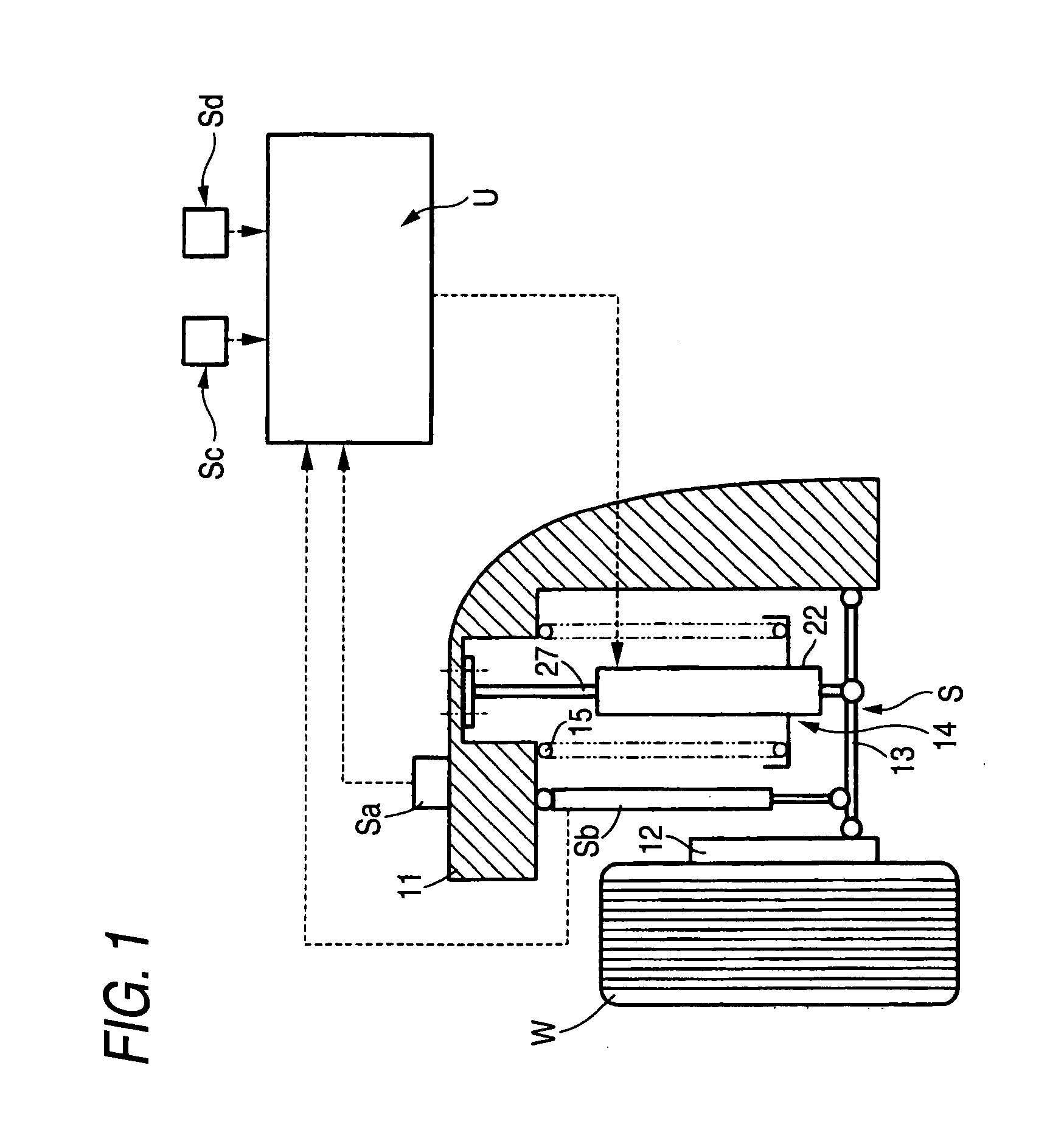
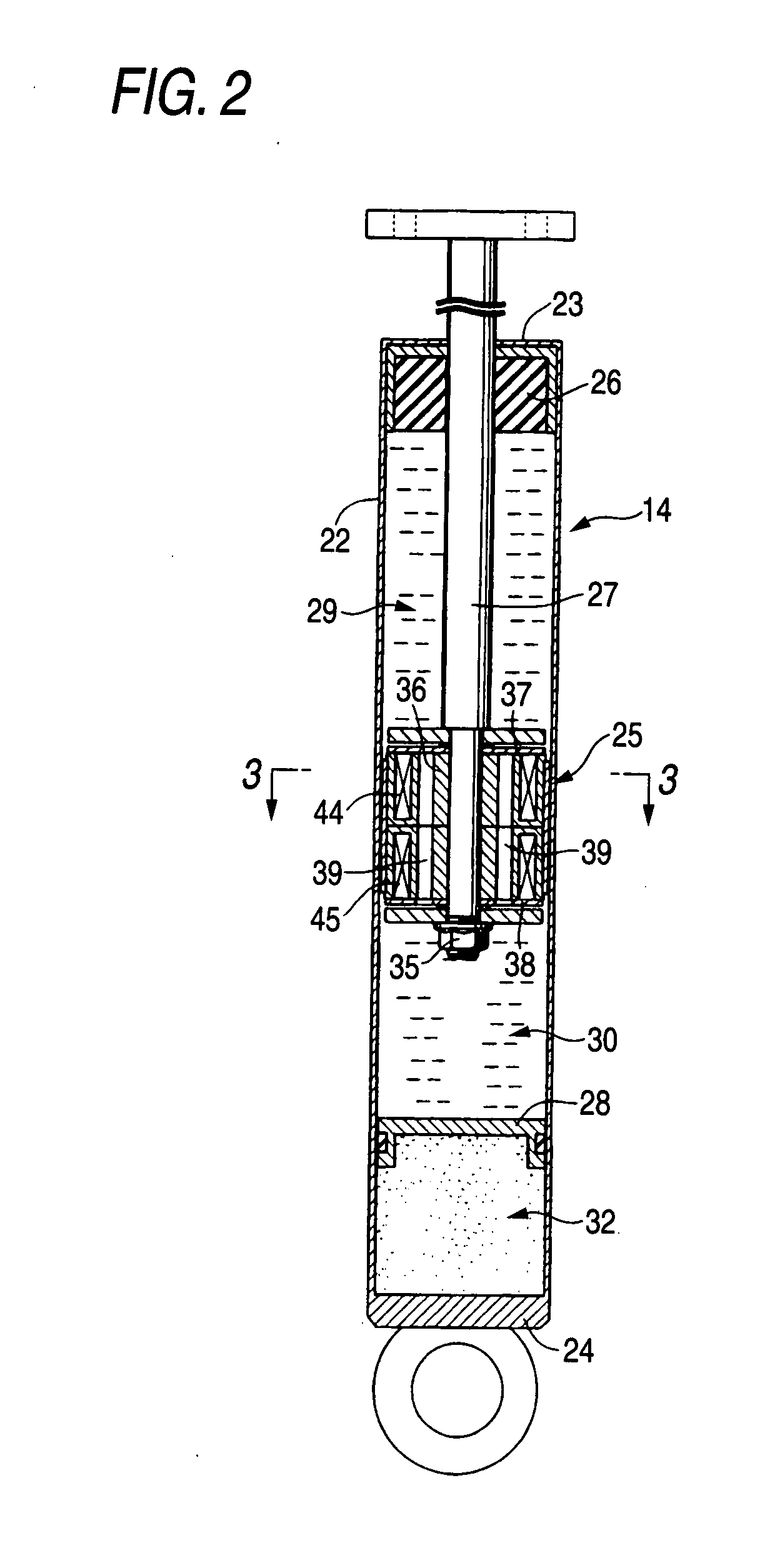
[0056] FIGS. 1 to 9 show a first embodiment of the invention, in which FIG. 1 is a front view of a suspension system in a vehicle, FIG. 2 is an enlarged sectional view of a variable attenuation power damper, FIG. 3 is an enlarged sectional view taken along a line 3-3 in FIG. 2, FIG. 4 is a sectional view taken along a line 4-4 in FIG. 3 (in non-excitation and low-speed time), FIG. 5 is a sectional view taken along a line 5-5 in FIG. 3 (in non-excitation and low-speed time), FIG. 6 is an action explanatory view corresponding to FIG. 4 (in excitation and high-speed time), FIG. 7 is an action explanatory view corresponding to FIG. 5 (in excitation and high-speed time), FIG. 8 is a graph showing a relation between piston speed and attenuation power, and FIG. 9 is a graph for explaining effects of magnetic viscous fluid.

[0057] As shown in FIG. 1, a suspension system S which suspends wheels...

second embodiment

[0081] Next, referring to FIG. 10, a second embodiment of the invention will be described.

[0082] In the first embodiment, the two piston bodies 36, 36 are overlaid in the axial direction and fastened integrally by the piston rod 27 and the nut 35. In the second embodiment, the two-divided piston bodies 36, 36 are formed integrally. In result, it is not necessary for a piston rod 27 to penetrate the piston body 36 in the axial direction, and the piston rod 27 is integrally fitted into the piston body 36 from the upper surface of the piston body 36 to the less than half position of the axial length of the piston body 36. Onto the lower surface of the piston body 36, a second valve plate 38, a shim 43 and a stopper plate 34 are fixed by a bolt 51 which is separate from the piston rod 27 and a nut 52. Between the lower end of the piston rod 27 and the upper end of the bolt 51, the piston body 36 becomes solid, and the volume of the piston body 36 increases correspondingly.

[0083] Onto ...

third embodiment

[0088] Next, a third embodiment of the invention will be described with reference to FIG. 11.

[0089] In the third embodiment, a cylindrical reservoir room 53 is formed so as to surround the periphery of a cylinder 22, and the lower end of the cylinder 22 and the lower end of the reservoir room 53 communicate with each other through plural communication holes 54. The inside of the cylinder 22 and the lower half portion of the reservoir room 53 are filled with oil, and the upper half portion of the reservoir room 53 is filled with gas.

[0090] A movable piston 25 which fits slidably into the cylinder 22 has substantially only the constitution of the lower half portion of the piston 25 (refer to FIG. 5) in the first embodiment. Namely, the movable piston 25 includes a piston body 36, a first coil 45, fluid passages 39, fluid passages 40, first orifices 47, a first valve plate 38, a shim 43, a stopper plate 34 and a piston ring 41. In the fluid passages 39, first check valves 55 which pe...


PUM


Abstract

An attenuation power control mechanism which changes opening of orifices 46, 47 of a piston 25 fitted into a cylinder 22 includes first and second valve plates 37, 38, and first and second coils 44, 45 which generate magnetic fields, whereby the first and second valve plates 37, 38 are deformed by the magnetic fields generated by the first and second coils 44, 45 to change the opening of the orifices 46, 47, so that the attenuation power of the damper can be controlled arbitrarily. At this time, the first valve plate 37 is deformed by the corresponding first coil 44, and the second valve plate 38 is deformed by the corresponding second coil 45.

Description

BACKGROUND OF THE INVENTION [0001] The present invention relates to a variable attenuation power damper which includes a magnetic alloy made valve plate and a coil which generates a magnetic filed, and changes the shape of the valve plate by the magnetic filed generated by the coil thereby to make arbitrary control of attenuation power possible. [0002] As well-known art, there is a variable attenuation power damper disclosed in the following Patent Document 1, in which a cylinder filled with viscous fluid is separated into first and second fluid chambers by a piston slidably fitted into the inside of the cylinder, and a spool valve which is opened and closed by a solenoid is arranged in a fluid passage which penetrates the piston and communicates the first and second fluid chambers with each other. According to this variable attenuation power damper, attenuation power of the damper can be controlled arbitrarily by energizing the solenoid and changing the opening of the spool valve. ...

Claims


Application Information

Patent Timeline
Patent Type & Authority Applications(United States)
IPC IPC(8): F16F9/53
CPCF16F9/535
Inventor NAKAJIMA, KIYOSHITOMARI, TATSUHIROSUKIGARA, TORU
Owner HONDA MOTOR CO LTD
Why Eureka
Try Eureka