Aqueous liquid clarification system
Inactive Publication Date: 2007-08-23
MARSH TAYLOR +1
11 Cites 9 Cited by
AI-Extracted Technical Summary
Problems solved by technology
Sedimentation without pre-treatment is rarely adequate for clarification of turbid water, as it does very little for removal of such fine particulate substances as clay, bacteria and the like.
Also, sedimentation results in sludge formation and thus requires means for disposal of the sludge.
However, granular media filtration virtually always requires chemical pre-treatment for effective turbidity removal.
The cost of the space and equipment required for installation of a conventional water treatment system of the type described above is considerable, as is the continuing cost of operation and maintenance of such a system.
Apparently, the use of polyelectrolytes in this patented process is essential, for if a flocculating agent alone is used in conjunctio...
Benefits of technology
[0026] The present invention represents an improvement ov...
Abstract
Disclosed is an impure aqueous liquid clarification system comprising a first plurality of polyacrylamide-housing means, the polyacrylamide being capable of flocculating impurities in impure aqueous liquid, this first plurality of housing means being joined in series and a second plurality of filter-housing means, each being capable of filtering impurities from the flow of aqueous liquid that have been flocculated therein by contact with the polyacrylamide in the first plurality of polyacrylamide-housing means, this second plurality of housing means being joined in series wherein, (a) the last of the polyacrylamide-housing means in the series of first plurality of housing means is joined in series to the first of the filter-housing means in the series of second plurality of housing means.
Application Domain
General water supply conservationTreatment involving filtration +12
Technology Topic
ChemistryPolyacrylamide +2
Image
Examples
- Experimental program(1)
Example
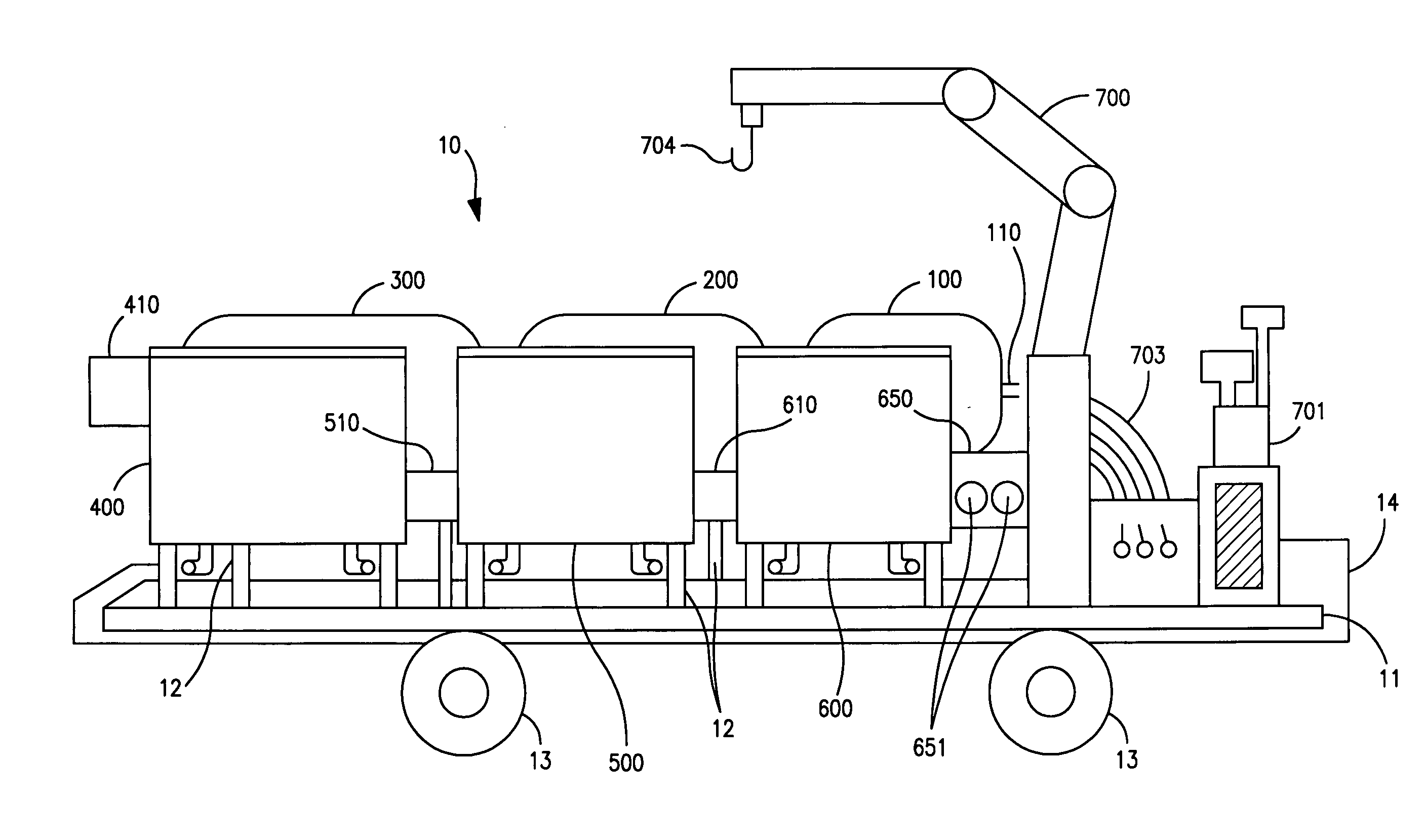
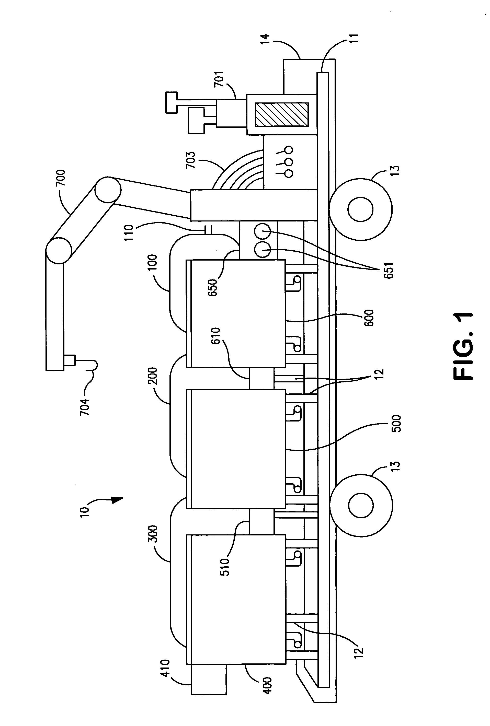
[0037] The invention will be described below with reference to the drawings for a preferred embodiment. It is to be understood that while a certain form of the invention is illustrated, it is not to be limited to the specific form or arrangement of parts herein described and shown. It will be apparent to those skilled in the art that various changes may be made without departing from the scope of the invention and the invention is not to be considered limited to what is shown in the drawings and described in the specification.
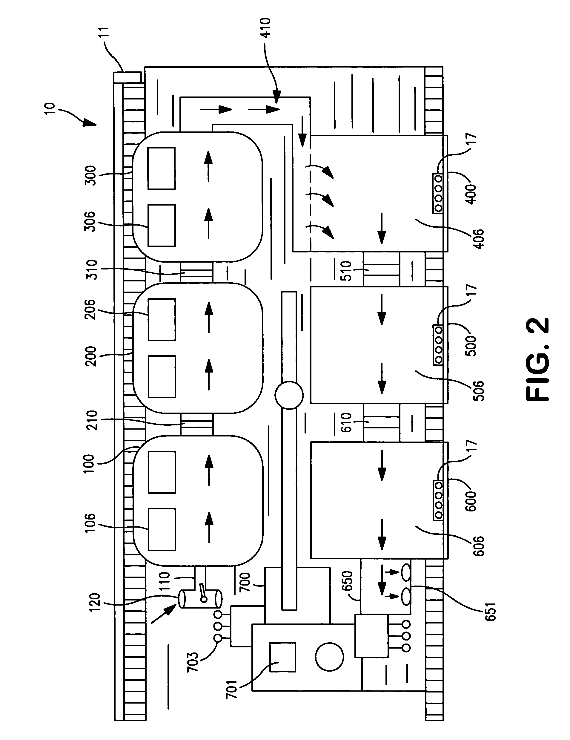
[0038] A preferred application of the invention comprises the clarification of a body, e.g., a pond of turbid water that has collected as a result of run-off from, e.g., a construction site. However, it is to be understood that the system and method of the invention are applicable for the clarification of any type of body of water, whether a running or standing body of turbid water. In the drawings, the arrows depict the direction of water flow through the system of the invention.
[0039] Referring to FIGS. 1-2, the clarification system 10 comprises a series of interconnected polyacrylamide-housings 100, 200 and 300 for accommodating a pressurized flow of turbid or impure water that enters the system via inlet 110 which is connected via connector 120 to a conduit (not shown) from the body of water to be clarified. In the embodiment shown, the water enters the system as a result of being pumped from a turbid pond (not shown) by a pump (also not shown). Each of the housings 100, 200 and 300 contain solid masses of polyacrylamide positioned therein so as to contact the turbid water as it is forced through the system by the pump. Contact with the polyacrylamide serves to flocculate at least some of the impurities contained in the water. The partly treated turbid water is forced through housing 100 and exits, then enters housing 200 via connector 210 where it contacts additional polyacrylamide, thereby flocculating additional impurities contained therein. The sequence is repeated when the further treated water exits housing 200 and enters housing 300 via connector 310. Preferably, polyacrylamide-housings 100, 200 and 300 are provided with lids 106, 206 and 306, respectively, to enable access to the interior thereof
[0040] It will be understood that additional polyacrylamide-housings may be positioned in the line, if desired; however, it is preferred to utilize three such polyacrylamide-housings to achieve optimum results.
[0041] The water containing flocculated impurities is then forced through connector 410 to the first of the filter-housings, 400. Therein, the fluid traverses a series of filter elements which permit passage of the water but retain thereon the flocculated impurities. The thus filtered fluid then enters, due to the pressure applied by the pump, filter-housing 500 via inlet 510. In filter-housing 500, the fluid is further contacted with an additional series of filters that remove still more flocculated impurities therefrom. After traversing housing 500, the fluid is forced into and through filter-housing 600 wherein it is submitted to a final filtering operation by a series of filters contained therein. Filter-housings 400, 500 and 600 are provided with hinged (17) lids 406, 506 and 606, respectively, to facilitate access to the interior thereof
[0042] Again, it will be understood that additional filter-housings may be positioned in the line, if desired; however, it is preferred to utilize three such filter-housings to achieve optimum results.
[0043] The clarified water then exits filter-housing 600 via outlet 650 wherein it is discharged from the system.
[0044] All of the polyacrylamide- and filter-housings are preferably rigidly attached to rectangular base support 11 by struts 12 to provide stable support for the system. It is preferred that the system be portable for ease of positioning near the body of turbid water to be clarified and for relocation to new positions. In a most preferred embodiment, base support 11 comprises the rectangular floor bed of a trailer 14 which is movable via wheels 13.
[0045] Although the various housings may be arranged in any desired fashion in order to achieve flocculation and removal of the turbidity-causing impurities, it is preferred that the housings be arranged in series as shown in FIGS. 1 and 2, i.e., wherein the first plurality of polyacrylamide-housing means is arranged longitudinally, in series, along one of the long sides of the rectangular base 11 and the second plurality of filter-housing means is arranged longitudinally along the opposite side of the rectangular base. More preferably, as shown in FIGS. 1 and 2 the pluralities of housing means are arranged such that the first of the polyacrylamide-housing means and the last of the filter-housing means are located nearer one of the short sides of the rectangular base 11 and the last of the polyacrylamide-housing means is joined in series to the first of the filter-housing means nearer the opposite short side of the rectangular base 11.
[0046] The water to be clarified is preferably transported to and through the system of the invention employing a floating pump assembly. Such floating pump assemblies are well known in the art and any suitable such pump may be used in the practice of the invention. A typical such pump assembly 900 is shown in FIG. 11 wherein pump 901 is depicted as supported by struts 906 on a platform 905 which is connected via connectors 910 to flotation devices 907. The assembly 900 is designed to float in the body of water to be clarified such that the pump head 902 is submerged to a depth sufficient to pump water in the body of water through conduit 909 to inlet 110 of polyacrylamide-housing 100. Preferably, a screen 903 is positioned over the pump head 902 to prevent large objects from being pumped in to the system of the invention. The pump may be powered by a power source 701 (FIGS. 1,2 and 10) connected thereto via power connectors 908. The floating pump assembly 900 is also preferably provided with attachment loop 904, by which it may be picked up and moved to another location on the body of water or removed altogether therefrom by a boom arm assembly (not shown) associated with the system of the invention.
[0047] Although a floating pump assembly has been depicted as the preferred means for delivering turbid water to the system of the invention, it will be understood by those skilled in the art that any suitable device capable of exerting sufficient fluid pressure to deliver the water to be clarified to and through the system may be employed in the practice of the invention.
[0048] As shown in FIGS. 1 and 2 it is also preferred to have a boom arm assembly 700 associated, preferably, firmly attached to and supported by base 11. The boom arm assembly is employed principally for lifting floating pump assembly 900 via hook means 704 which is adapted to engage attachment loop 904 of pump assembly 900. It will be understood by those skilled in the art that any conventional, suitable boom arm assembly may be employed in the practice of the invention. Preferably the boom arm assembly is an articulated, hydraulically-operated boom arm assembly. As depicted in FIGS. 1,2 and 10, the boom arm assembly is operated by the hydraulic line assembly 703 connected via power connector 702 to power source 701. Power source 701 is also preferably firmly attached to base 11 for stability purposes.
[0049] Although boom arm assembly 700 has been shown for the purpose of positioning the floating pump assembly 900, it will be understood by those skilled in the art that any suitable device may be employed for this purpose without departing from the scope of the invention.
[0050] The polyacrylamide-housings and the function thereof are described in greater detail hereinafter with special reference to FIGS. 3-6.
[0051] Referring to FIG. 3, first polyacrylamide-housing 100 is equipped with impure water inlet 110. The water is conveyed from the impure water source via conduit 909 which is connected to inlet 110 via connector 120. The connection is provided with snorkel means 124 for the purposes of regulating air inlet and water pressure. The housing 100 is also outfitted with lids 106 to gain access to the interior thereof and struts 12 to stabilize the housing on the base deck (not shown). Housing 100 is also provided with outlet 108 for the removal from the bottom thereof of sediment that collects during the practice of the invention. Housing 100 is provided with outlet 210 for transmitting water that has run therethrough to housing 200 (not shown).
[0052] Polyacrylamide-housings 100, 200 and 300 are preferably cylindrical in shape as shown in the drawings since that configuration provides optimum clarification of the impure water. It will be understood by those skilled in the art, however, that any suitable configuration may be employed for this purpose without departing from the scope of the invention.
[0053] Most preferably, as best seen in FIGS. 4 and 5, all of the polyacrylamide-housings (100 and 200) except the last one in the series (300) contain within them preferably rectangular interior housing-conduits 111 and 112 (in 100) through which the impure water flows from one polyacrylamide housing to the next, i.e., from 100 to 200. The rectangular conduit is rigidly supported within the polyacrylamide-housing and extends coaxially within the polyacrylamide-housing through the cylindrical tanks, at least to the entrance of the last cylindrical tank. Rectangular conduit 111,112 contains porous screen-type elements 115 adapted to releasably house solid masses of polyacrylamide 50 and to allow passage therethrough of the impure aqueous liquid in contact with each element of polyacrylamide 50 into the last cylindrical tank.
[0054] The rectangular housing conduit is rigidly supported within the cylindrical tanks by struts 116 such that a substantially open space exists between all of the outer walls of the rectangular housing conduit and the inner walls of the cylindrical tanks.
[0055] Preferably the rectangular housing conduit is divided into first and second coaxially extending sections 111 and 112 so as to provide an open space therebetween and to allow impure aqueous liquid entering the open space from the first section 111 to at least partially spill into the cylindrical tank 100, and at least partially fill and circulate within the cylindrical tank 100 before exiting the tank through said second section 112. The interior walls of cylindrical tank 100 are also preferably fitted with a plurality of porous screen-type cages 113 for releasably housing polyacrylamide masses 50 through which the impure water spilling into the interior of the cylindrical tank from first section 111 passes to facilitate additional flocculation of impurities before exiting through second section 112.
[0056] It will be understood that sections 111 and 112 may be joined to form one continuous rectangular housing conduit and that the two section element (111 and 112) is shown as the preferred embodiment. Moreover, it will also be understood that cylindrical tank 200 and any additional cylindrical tanks, except, optionally, the last one may be identically constructed. Rectangular housing conduits 111 and 112 are provided with lids 114 to allow access into the interior thereof.
[0057] Optionally and preferably, the last cylindrical tank in the series is not constructed to house the above-described rectangular housing conduits. As shown in FIG. 6, it is preferred that the last tank 300 be divided into sections 311 by walls 313 which extend alternately from one cylindrical side of the tank toward the other leaving alternately spaced flow passages for the water on each side of the tank, as shown. The walls 313 are provided with holes 312 near the walls from which they extend to provide alternately spaced flow passages on those sides as shown. The walls 313 are provided with porous screen elements 315, each releasably containing solid polyacrylamide 50 for contact with the water flowing therethrough as in tanks 100 and 200. The bottom of tank 300 is also provided with outlets 308 for releasing sediment therefrom. Tank 300 is constructed as depicted in FIG. 6. i.e., is transversely divided by liquid flow diverting walls 313, provided with holes 312, to force a tortuous flow of impure aqueous liquid from inlet 310 from tank 200 therethrough to outlet 410 to first filter-housing 400, thereby ensuring maximum contact between the impure water and the polyacrylamide flocculent.
[0058] Filter-housings 400, 500 and 600 are preferably rectangular in shape as shown in the drawings since that configuration provides optimum clarification of the impure water. It will be understood by those skilled in the art, however, that any suitable configuration may be employed for this purpose without violating the spirit of the invention.
[0059] As shown in FIG. 7, impure, flocculant containing water flows from outlet 410 from polyacrylamide-housing 300 into filter-housing 400. Optionally, and preferably, this first filter-housing 400 that the water enters is constructed as shown in FIG. 7. The impure water enters filter-housing 400 from outlet 410 into trough 412 that runs along the top of filter-housing 400. The bottom surface of the trough 412 is provided with holes (not shown) that allow the impure water to fall by gravity in waterfall fashion into the interior of housing 400. The pressure exerted by the pump 900 forces the water through filter housing 400 in the direction depicted by the arrows. The filter-housing 400 is provided with multiple brackets 401 on opposing perpendicular walls 402 aligned with each other and spaced for releasably installing multiple individual filter means 640 that are positioned transverse to the flow of impure aqueous liquid therein. After operation of the system for a predetermined length of time, the filters 640 are removed, cleared of flocculated impurities and reinserted into brackets 401 for further filtering of the water flow. The bottom of housing 400 is provided with sediment outlets 408. The water flow that has been at least partially filtered in housing 400 flows through outlet 510 to the next filter-housing in line.
[0060] The next housing filter in line, 500, is constructed similarly to housing 400 except that the incoming water does not enter via a trough. Instead, as shown in FIG. 8 the partially filtered water enters filter housing 500 via outlet 510 from housing 400 and flows under pressure as described above in the direction of the arrows through filters 504, releasably mounted in brackets 502 so as to be transverse to the flow of water through housing 500. Lid 506 is provided for access to the interior of the housing. Sediment-releasing outlets 508 are provided at the bottom of the housing. After further filtration in housing 500, the water flows through outlet 610 into the next filter housing in line.
[0061] The thusly further purified water then flows through outlet 610 from housing 500 to filter housing 600 as shown in FIG. 9, which is constructed similarly to housing 500. Housing 600 is provided with brackets 602 designed to releasably position filter elements 640 transverse to the flow of water in housing 600. The clarified water exits the system via outlet 650. The housing is provided with a lid 606 for interior access and sediment releasing outlets 608.
[0062] It will be understood by those skilled in the art that any suitable filtering means may be employed in the practice of the invention. It is preferred to employ screen-type filters as depicted in FIG. 9 with openings therein of a size to trap the impurities in the water flocculated by the polyacrylamide but sufficiently large to allow optimum flow of water through the system. The filter screens are constructed so as to occupy substantially the entire planar rectangular area within the filter housings transverse to the flow of water therethrough. It will be understood by those skilled in the art that the rate of flow of water through the system of the invention is dependent upon multiple variables, including, but not limited to, the pressure generated by the pump 900, the number of polyacrylamide blocks in the polyacrylamide-housings 100, 200 and 300, the number of filters in filter housings 400, 500 and 600, the frequency of cleaning the filters, and the like.
[0063] Referring to FIG. 10, boom arm assembly 700 engages and picks up pump 900 (FIG. 11) by means of hook 704 and positions the floating pump in its desired location in the body of water to be clarified (not shown). Impure water is transmitted under pressure to inlet means 110 (FIGS. 2 and 3) by the pump 900, which is powered by power source 701 through power connectors 908 (which also powers boom arm assembly 700 by means of power connector 702 and hydraulic lines 703). After passage through the system of the invention, the clarified water exits the system via outlet 650 from final filter housing 600. Outlet 650 is provided with connection elements 651 which may be connected to hoses for transmitting the water to any desired location, including the source of turbid water itself. The rate of exit of the clarified water may be regulated by valve means 652. If desired, extensible struts 22 may be positioned on the underside of base-deck 11 to raise the system to an elevation such that the wheels 13 of the trailer are off the ground and the system is further stabilized for operation.
[0064] The present invention is not limited to the above embodiments and various changes and modifications can be made within the spirit and scope of the present invention. Therefore to apprise the public of the scope of the present invention, the following claims are made.
PUM
Property | Measurement | Unit |
Length | ||
Force | ||
Pressure |
Description & Claims & Application Information
We can also present the details of the Description, Claims and Application information to help users get a comprehensive understanding of the technical details of the patent, such as background art, summary of invention, brief description of drawings, description of embodiments, and other original content. On the other hand, users can also determine the specific scope of protection of the technology through the list of claims; as well as understand the changes in the life cycle of the technology with the presentation of the patent timeline. Login to view more.