Electric machine

a technology of electric machines and field poles, applied in the field of electric machines, can solve the problems of reducing motor efficiency, demagnetizing the field pole magnet, and eddy current loss occurring in the field pole unit constitute an appreciable part of the total energy loss, and achieve the effect of reducing eddy current loss

Inactive Publication Date: 2007-08-23
MITSUBISHI ELECTRIC CORP
View PDF14 Cites 57 Cited by
  • Summary
  • Abstract
  • Description
  • Claims
  • Application Information

AI Technical Summary

Benefits of technology

[0009]In light of the aforementioned problems of the prior art, it is an object of the invention to pr

Problems solved by technology

In large-sized motors rated over a few kilowatts, however, eddy current loss occurring in a field pole unit constitutes an appreciable part of a total energy loss.
For example, neodymium-iron-boron (Nd—Fe—B) permanent magnets often used as field pole magnets today tend to produce eddy currents as compared to ferrite permanent magnets, and thus have a problem that an eddy current loss occurring in a field pole unit causes a reduction in motor efficiency and a temperature increase of the field pole unit results in demagnetization of the field pole magnets.
Even if the field pole magnets are not demagnetized, the temperature increase of the field pole unit would cause a reduction in the remnant magnetic flux density and a resultant decrease in a total quantity of magnetic flux produced by the field pole magnets.
To make up for a loss in motor power caused by this temperature increase of the field pole unit, it is necessary to flow an increased amount of armature

Method used


Image

  • Electric machine
  • Electric machine
  • Electric machine

Examples


first embodiment

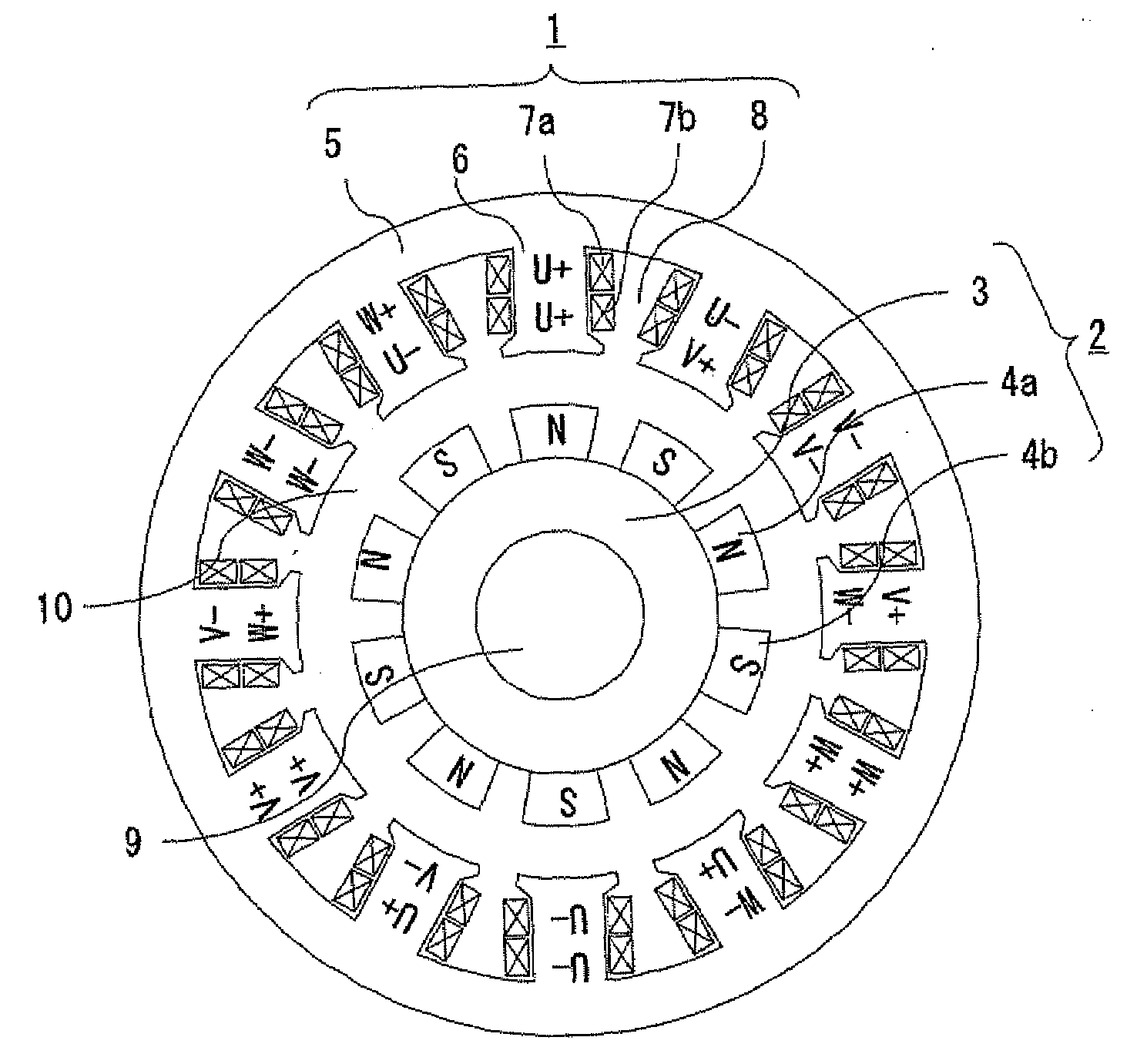
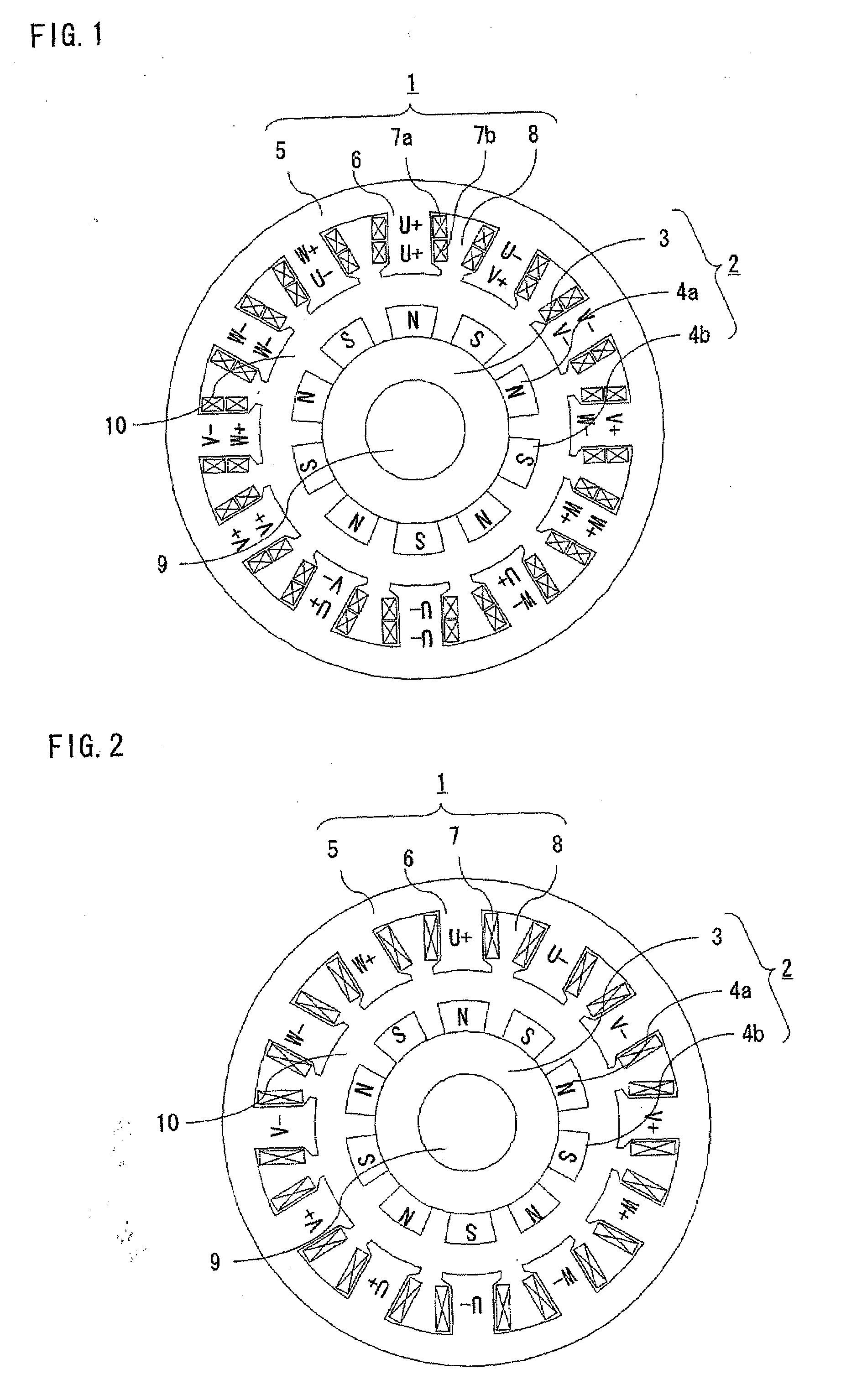
[0032]FIG. 1 is a sectional diagram showing the structure of an electric machine according to a first embodiment of the invention. This electric machine is a 3-phase, 10-pole, 12-tooth rotating electric machine including an armature 1 and a field pole unit 2 which are disposed relatively rotatably by means of retaining devices, such as bearings, with a magnetic gap 10 created in between. The field pole unit 2 includes a field pole core 3 mounted on a shaft 9 and five pairs (ten in total) of north-pole (N-pole) permanent magnets 4a and south-pole (S-pole) permanent magnets 4b, which may be referred to simply as the permanent magnets 4 collectively, attached to the field pole core 3. While each of the permanent magnets 4a, 4b constitutes one magnetic pole as illustrated in FIG. 1, the electric machine is not specifically limited to this example in terms of permanent magnet configuration. Also, although the permanent magnets 4a, 4b are arranged on an outer surface of the field pole cor...

second embodiment

[0046]FIG. 9 is a sectional diagram showing the structure of an electric machine according to a second embodiment of the invention, in which elements identical or similar to those of the first embodiment are designated by like reference numbers. While the above-described electric machine of the first embodiment is a 10-pole, 12-tooth rotating electric machine, the electric machine of the second embodiment shown in FIG. 9 is a 3-phase, 20-pole, 24-tooth rotating electric machine. If the number of poles “P” and the number of teeth “Q” are expressed by P=5n and Q=6n, respectively, where “n” is any even number, the coils 7a, 7b should be wound around the successive teeth 6 with phase relationships and winding polarities arranged in the order of U+ / U+, U− / V+, V− / V−, W− / V+, W+ / W+, W− / U+, U− / U−, U+ / V−, V+ / V+, W+ / V−, W− / W− and W+ / U− in the clockwise direction from top as illustrated in FIG. 9, which is the same as shown in FIG. 1 but repeated twice.

[0047]In the structure of this embodiment,...

third embodiment

[0048]FIG. 11 is a sectional diagram showing the structure of an electric machine according to a third embodiment of the invention which is a 3-phase, 14-pole, 12-tooth rotating electric machine, in which elements identical or similar to those of the foregoing embodiments are designated by like reference numbers. Although the rotating electric machine of this embodiment is a 14-pole type, an armature 1 has the same structure as that of the first embodiment. In this rotating electric machine, a 7th-order spatial harmonic component becomes as a synchronized component. Stated more generally, the synchronized component is a (7n / 2)th-order spatial harmonic component in this embodiment if the number of poles “P” and the number of teeth “Q” are expressed by P=7n and Q=6n, respectively, where “n” is any even number.

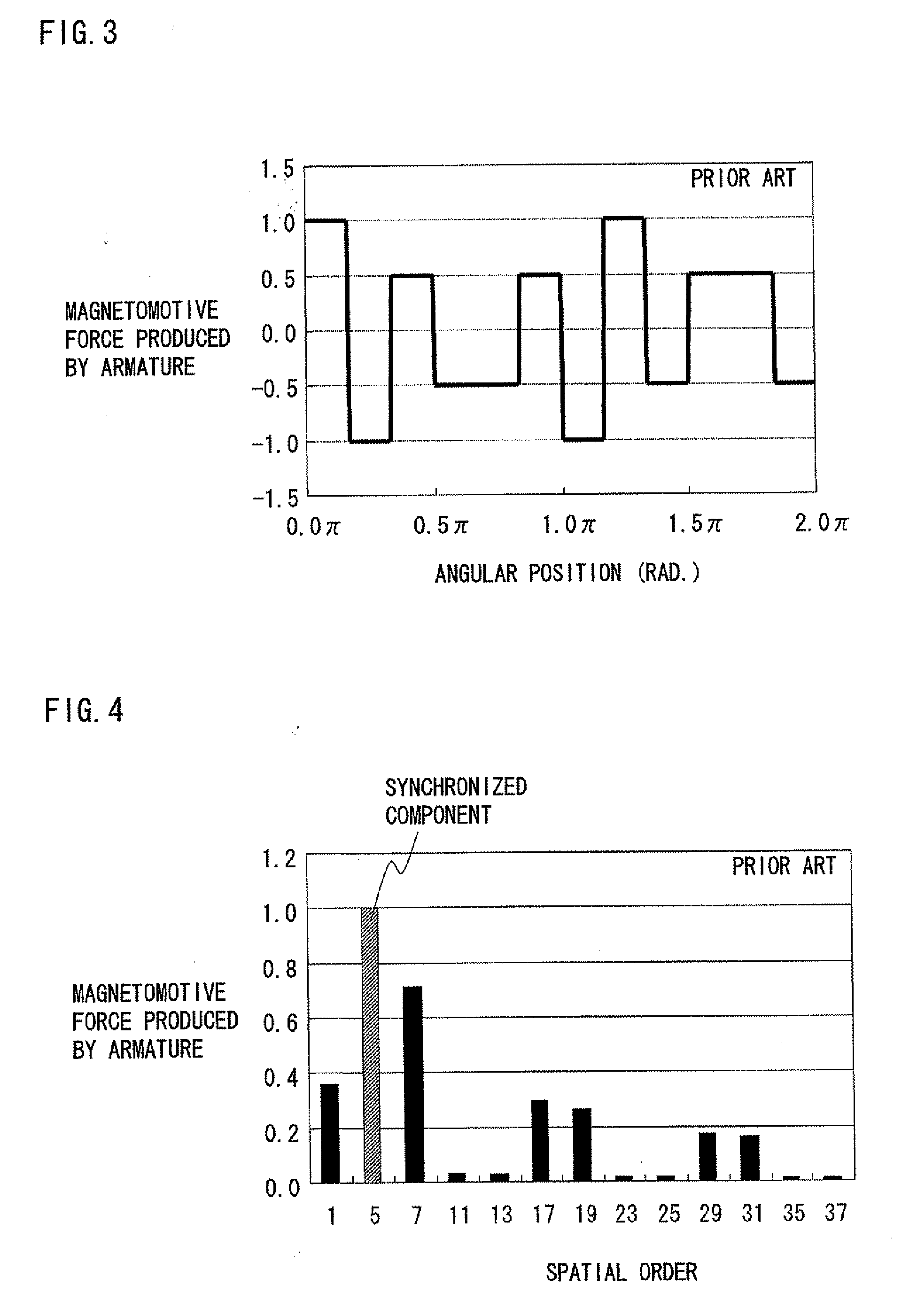
[0049]FIG. 12 is a graph showing components of individual orders of magnetomotive forces produced by the armature 1 of the third embodiment together with the components of indivi...


PUM


Abstract

In a rotating electric machine including a field pole unit having ten magnetic poles (P=10) and an armature having twelve teeth (Q=12), armature coils are wound around the successive teeth with phase relationships and winding polarities arranged in the order of U+/U+, U−/V+, V−/V−, W−/V+, W+/W+, W−/U+, U−/U−, U+/V−, V+/V+, W+/V−, W−/W− and W+/U−, where “U,”“V” and “W” represent three phases of the individual armature coils while “+” and “−” denote winding polarities. Among all harmonic components of magnetomotive forces produced by the armature coils, harmonic components of orders lower than a synchronized component can be reduced in this rotating electric machine. This structure decreases eddy currents flowing in the field pole unit, resulting lower eddy current loss in the field pole unit of the rotating electric machine.

Description

BACKGROUND OF THE INVENTION[0001]1. Field of the Invention[0002]The present invention relates to an electric machine, such as a rotating electric machine or a linear motor, as well as to a technique for reducing eddy current loss which occurs in a field pole unit.[0003]2. Description of the Background Art[0004]Conventionally, a rotating electric machine provided with a field pole unit having a plurality of permanent magnets and an armature including concentratedly wound armature coils has been used in various applications. “Concentrated winding” is a coil-winding structure in which coils are concentratedly wound on teeth of an armature. As a result of recent advances in machine-assisted automatic coil-winding techniques, concentrated winding is widely used today in the manufacture of rotating electric machines, chiefly for compact motors including servomotors. A majority of energy loss occurring in such small-sized motors is attributed to copper loss, iron loss and mechanical loss, ...

Claims


Application Information

Patent Timeline
IPC IPC(8): H02K41/00H02K3/00
CPCH02K3/28H02K21/222H02K21/16
Inventor ITO, KAZUMASANAKA, KOUKINAKANO, MASATSUGUKOBAYASHI, MANABU
Owner MITSUBISHI ELECTRIC CORP
Why Eureka
Try Eureka