
Downhole power generation and communications apparatus and method

Inactive Publication Date: 2007-08-23
SCHLUMBERGER TECH CORP
View PDF16 Cites 58 Cited by
  • Summary
  • Abstract
  • Description
  • Claims
  • Application Information

AI Technical Summary

Benefits of technology

[0010] The deficiencies of the prior art can be addressed by an apparatus to communicate with a downhole sensor. The apparatus preferably includes a surface unit including a pressure wave generator and a signal processing unit. The apparatus also preferably includes a downhole energy converter configured to convert pressure fluctuations from the pressure wave generator to electrical energy. The apparatus also preferably includes an energy storage device configured to store electrical energy from said energy converter. The apparatus also preferably includes a control module configured to receive data from the downhole sensor and to transmit the data to the signal processing unit through a pressure wave telemetry unit.
[0011] The deficiencies of the pr

Problems solved by technology

One form of communications that continually challenges the industry relates to the communication between surface and downhole equipment.
Therefore, systems that rely on batteries or other stored power devices are generally not sufficient for the life of smart or other permanent completions systems.
Currently, the monitoring of smart or permanent completions equipment is periodic in nature but this is subject to change as more detailed and complex measurements are enabled.
As the amount of data processing increases downhole, so do the power demands of such equipment.
While much effort has been spent on wireline communication, its inherent high telemetry rate and power transmission capacity is not always needed and very often does not justify the high cost of deploying and installing thousands of feet of permanent or temporary wireline in a wellbore.
While such systems are promising, they suffer from similar cost problems resulting from their short or long term placement.
This requirement however prevents the use of MWD techniques in operations during which a flowing medium is not available.
Most previously known approaches are either severely limited in scope and operability or require downhole transmitters that consume large amounts of energy.

Method used


Image

  • Downhole power generation and communications apparatus and method
  • Downhole power generation and communications apparatus and method
  • Downhole power generation and communications apparatus and method

Examples


Embodiment Construction

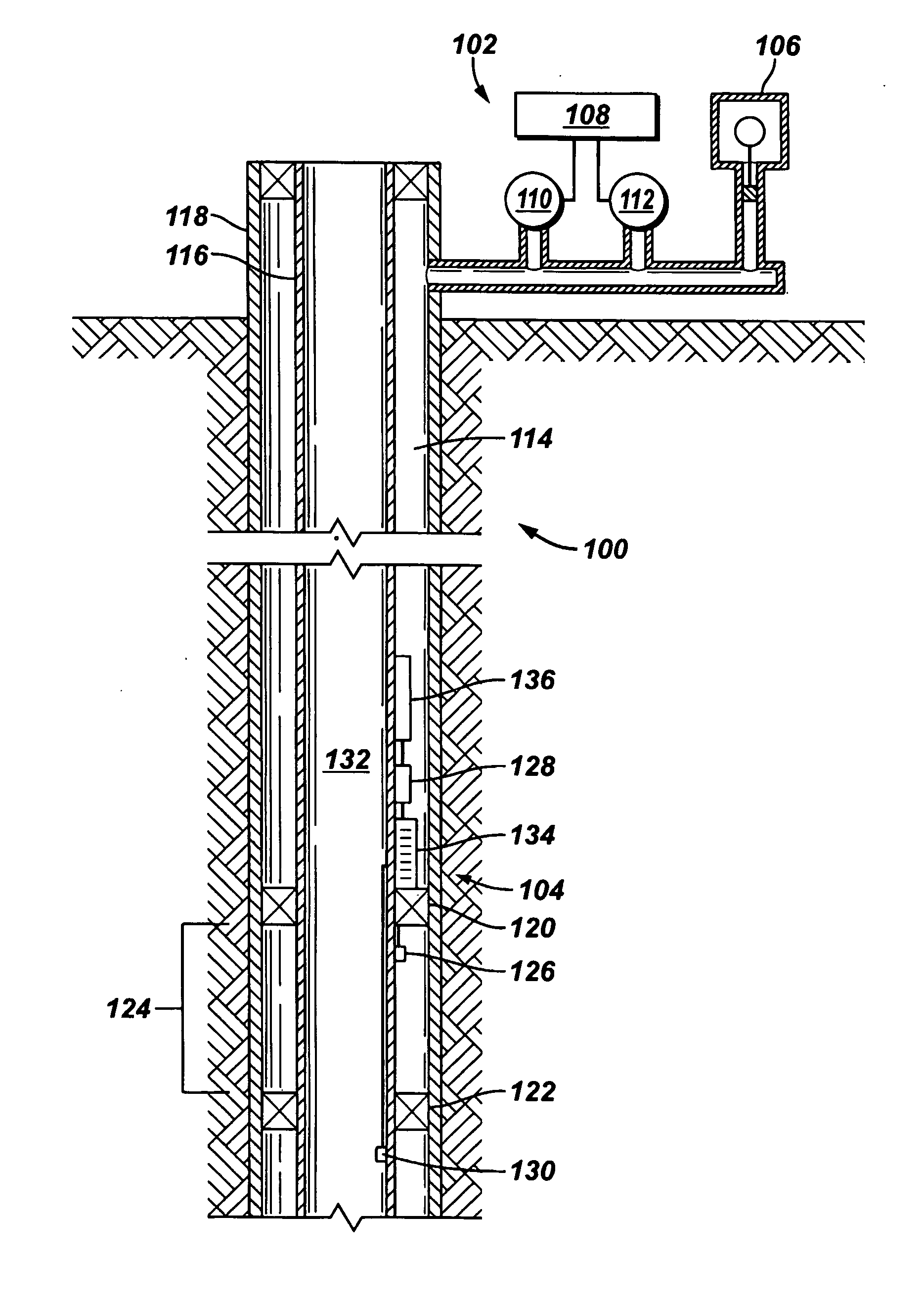
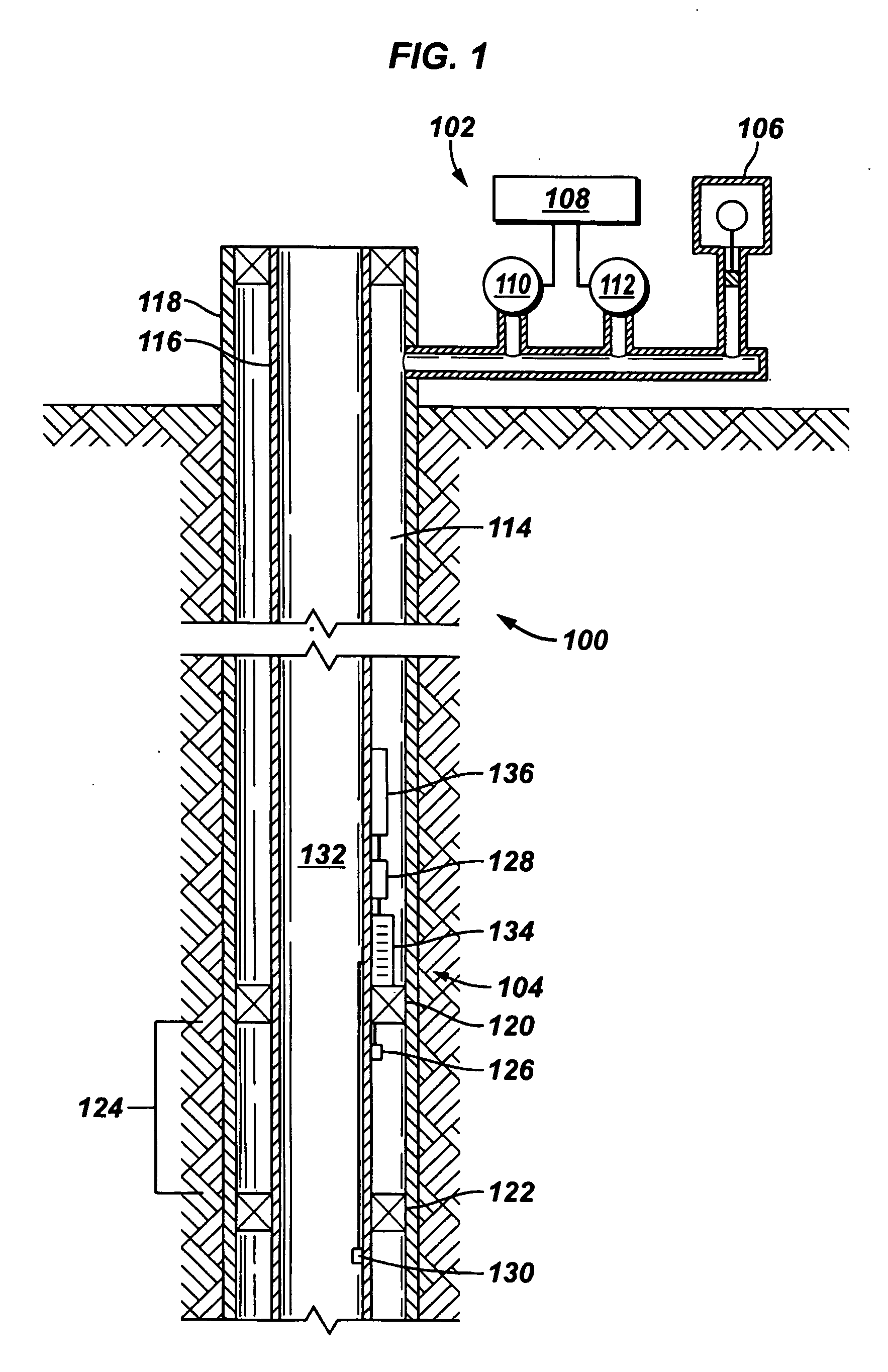
[0020] Referring initially to FIG. 1, a downhole communications system 100 is shown schematically. Downhole communications system 100 preferably includes a surface unit 102 and a downhole communications package 104. Surface unit 102 preferably includes a pressure wave generator 106, a signal processing unit 108, and pressure transducers 110, 112. Pressure wave generator 106 is shown as a piston-type pressure generator that includes a motor driven piston producing a reciprocal movement within a cylinder but may be of any type known in the art. Surface unit transmits, receives, and analyzes pressure wave signals to and from communications package 104.

[0021] Communications package 104 is shown located downhole in an annulus 114 between strings of production tubing 116 and casing 118. Ideally, packers 120, 122 isolate sections of strings 116, 118 so that distinct measurements in a zone of investigation 124 can be taken by downhole sensor package 126 (downhole sensor). Downhole sensor p...


PUM


Abstract

Apparatuses and methods to power and communicate with downhole sensors are presented. Preferred embodiments of the present invention includes energizing a downhole sensor with a surface pressure wave generator and a downhole mechanical to electrical energy converter. Preferred embodiments of the present invention also include transmitting data measured from a downhole sensor to a surface unit through modulation of surface-generated pressure waves.

Description

BACKGROUND OF THE INVENTION [0001] The present invention generally relates to communications with the long-term placement of downhole completions equipment. More particularly, the present invention relates to an apparatus and method to wirelessly communicate with downhole completions equipment. More particularly still, the present invention relates to methods and apparatuses to wirelessly communicate with and generate power for downhole completions equipment, particularly those permanently installed in the well. [0002] Because of the variety of sensor and measurement devices used in oilfield drilling and production operations, various communication systems and schemes are often necessary. One form of communications that continually challenges the industry relates to the communication between surface and downhole equipment. Particularly, it is often necessary to retrieve data from downhole equipment and sensors for processing and decision-making at the surface. Operations such as dri...

Claims


Application Information

Patent Timeline
IPC IPC(8): G01V3/00E21B41/00E21B47/14
CPCE21B47/14E21B41/0085
Inventor HUANG, SONGMINGMONMONT, FRANCKSADIKOGLU, KASIM
Owner SCHLUMBERGER TECH CORP
Learn More