Liquid ejection head and image forming apparatus including liquid ejection head

a liquid ejection head and image forming technology, which is applied in the direction of printing, inking apparatus, etc., can solve the problems of unstable ejection direction slow actual ejection speed of small liquid droplets, and inability to achieve sufficient control of recording through the use of nozzles, so as to reduce the frequency of maintenance, such as liquid (ink) replacement, and achieve good balance. , the effect of reducing the number of times of maintenan

Inactive Publication Date: 2007-08-23
FUJIFILM CORP
View PDF3 Cites 12 Cited by
  • Summary
  • Abstract
  • Description
  • Claims
  • Application Information

AI Technical Summary

Benefits of technology

[0024]In this aspect of the present invention, the running costs can be reduced, and the frequency of maintenance, such as liquid (ink) replacement, can be reduced.
[0025]According to the present invention, in a liquid ejection head having a nozzle (large nozzle) which ejects a large liquid droplet and a nozzle (small nozzle) which ejects a small liquid droplet, it is possible to maintain a good balance betwee...

Problems solved by technology

In this case, in a system based on heating elements in particular, it is difficult to achieve sufficient control of recording by means of nozzles having one and the same structure (a common structure).
For example, when the ejection speed is adjusted on the basis of large liquid droplets in order for the large liquid droplets to be ejected at ...

Method used


Image

  • Liquid ejection head and image forming apparatus including liquid ejection head
  • Liquid ejection head and image forming apparatus including liquid ejection head
  • Liquid ejection head and image forming apparatus including liquid ejection head

Examples


example

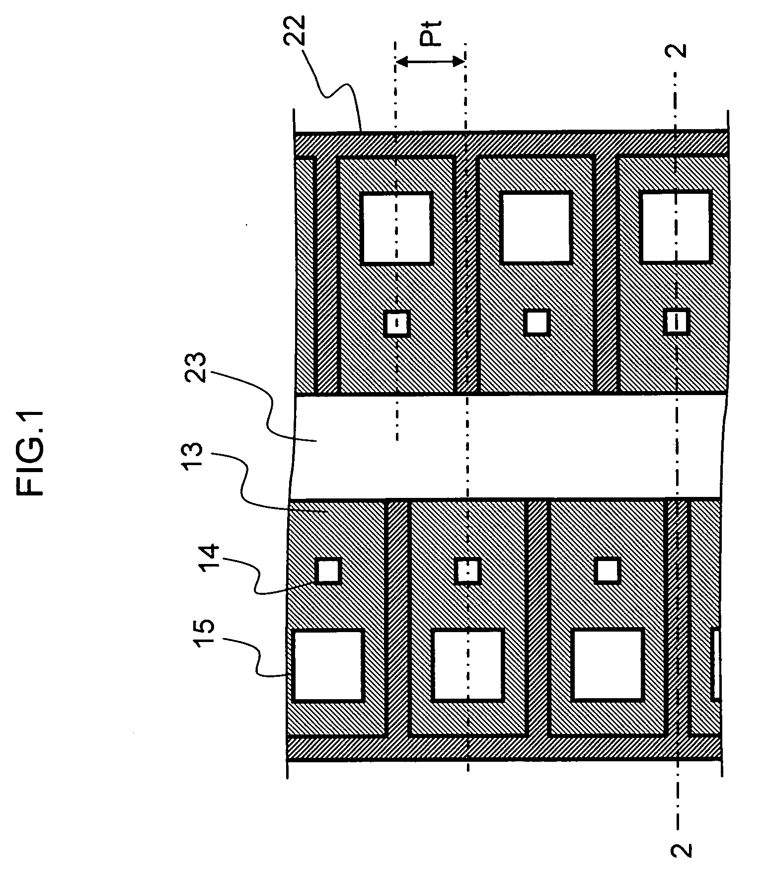
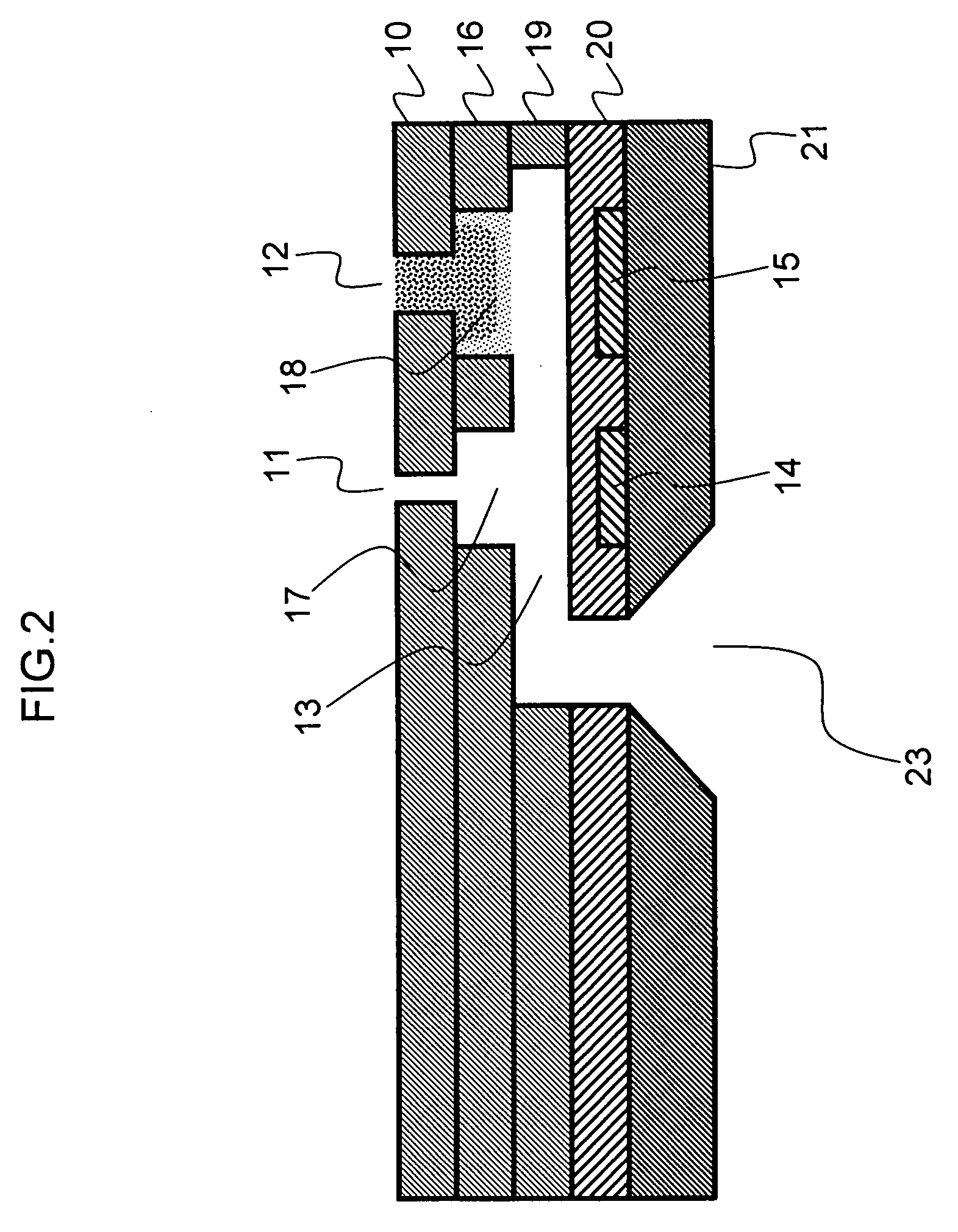
[0044]Below, an example of the liquid ejection head according to the present embodiment is described with reference to FIGS. 1 and 2.

[0045]In the liquid ejection head of the present example, the small nozzles 11 have a nozzle diameter of 20.3 μm, the large nozzle 12 have a nozzle diameter of 28.2 μm. The heaters 14 opposing the small nozzles 11 have a substantially square shape having an edge length of 23 μm, and the heaters 15 opposing the large nozzles 12 have a substantially square shape having an edge length of 31 μm.

[0046]The length of the small nozzles 11, the length of the large nozzles 12, and the thickness of the nozzle plate 10 are 7 μm. The height of the small nozzle liquid chambers 17, the height of the large nozzle liquid chambers 18, and the thickness of the nozzle liquid chamber plate 16 are 5 μm. The height of the individual flow channels 13 and the thickness of the individual flow channel plate 19 are 8 μm.

[0047]The nozzle pitch Pt shown in FIG. 1 is 84.6 μm, and th...


PUM


Abstract

The liquid ejection head includes: a large nozzle which ejects a large droplet of liquid; a small nozzle which has a smaller nozzle diameter than the large nozzle and ejects a small droplet of the liquid which has a smaller volume than the large droplet; a first heat generating element and a second heat generating element which are provided opposite to the large nozzle and the small nozzle respectively, and apply thermal energy to the liquid in at least one individual flow channel that supplies the liquid to the large nozzle and the small nozzle in such a manner that a bubble causing the large droplet of the liquid to be ejected from the large nozzle and a bubble causing the small droplet of the liquid to be ejected from the small nozzle respectively; a first liquid chamber which is provided between the large nozzle and the at least one individual flow channel and between the large nozzle and the first heat generating element corresponding to the large nozzle.

Description

BACKGROUND OF THE INVENTION[0001]1. Field of the Invention[0002]The present invention relates to a liquid ejection head and an image forming apparatus comprising a liquid ejection head, and more particularly, to the stabilization of ink in a liquid ejection head capable of forming high-definition images.[0003]2. Description of the Related Art[0004]As an image forming apparatus in the related art, an inkjet printer (inkjet recording apparatus) is known, which includes an inkjet printer head (liquid ejection head) having an arrangement of a plurality of liquid ejection nozzles and which records images on a recording medium by ejecting ink (liquid) from the nozzles toward the recording medium while the relative movement between the inkjet head and the recording medium is performed.[0005]The inkjet head of the inkjet printer ejects ink, for example, either by using piezoelectric elements or by generating bubbles by means of heating elements.[0006]For example, in an inkjet head which eje...

Claims


Application Information

Patent Timeline
IPC IPC(8): B41J2/04
CPCB41J2/1404B41J2/14056B41J2202/21B41J2002/14475B41J2/2125
Inventor KUSUNOKI, NAOKI
Owner FUJIFILM CORP
Why Eureka
Try Eureka