Method of eye examination by optical coherence tomography

a tomography and optical coherence technology, applied in image analysis, medical science, image enhancement, etc., can solve the problems of limited ability to sufficiently map the optic nerve layer, inability to see the choroid layer, and inability to provide qualitative interpretation of eye structural changes

a tomography and optical coherence technology, applied in image analysis, medical science, image enhancement, etc., can solve the problems of limited ability to sufficiently map the optic nerve layer, inability to see the choroid layer, and inability to provide qualitative interpretation of eye structural changes

US20070195269A1Active Publication Date: 2007-08-23OPTOVUE

Image

  • Method of eye examination by optical coherence tomography
  • Method of eye examination by optical coherence tomography
  • Method of eye examination by optical coherence tomography

Examples


Embodiment Construction

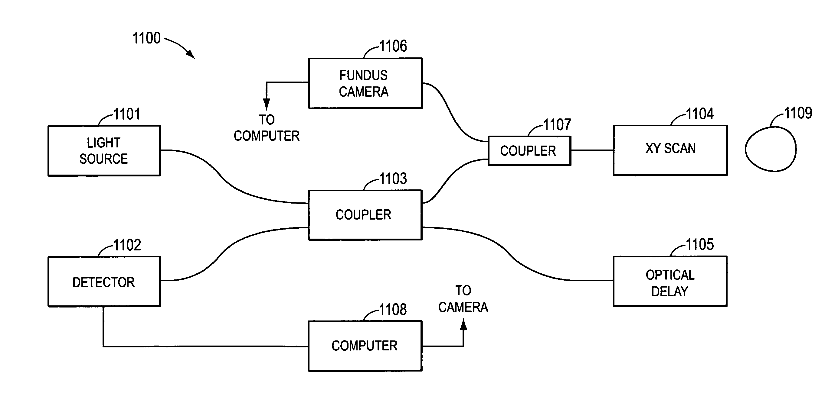
[0029] Embodiments of the current invention can be utilized for evaluating the eye tissue structure for diagnosing eye diseases. Some embodiments utilize an Optical Coherence Tomography (OCT) image, a fundus image, and an algorithm associated with both image modalities to map out the eye tissue structure accurately. Some embodiments of the invention provide an image of the eye tissue structure substantially absent of artifacts caused by eye motion or image distortion caused by light absorption of the retinal blood vessels. The current disclosed eye examination methods can be utilized in the diagnoses of eye pathologies in the optic nerve head, for example Glaucoma.

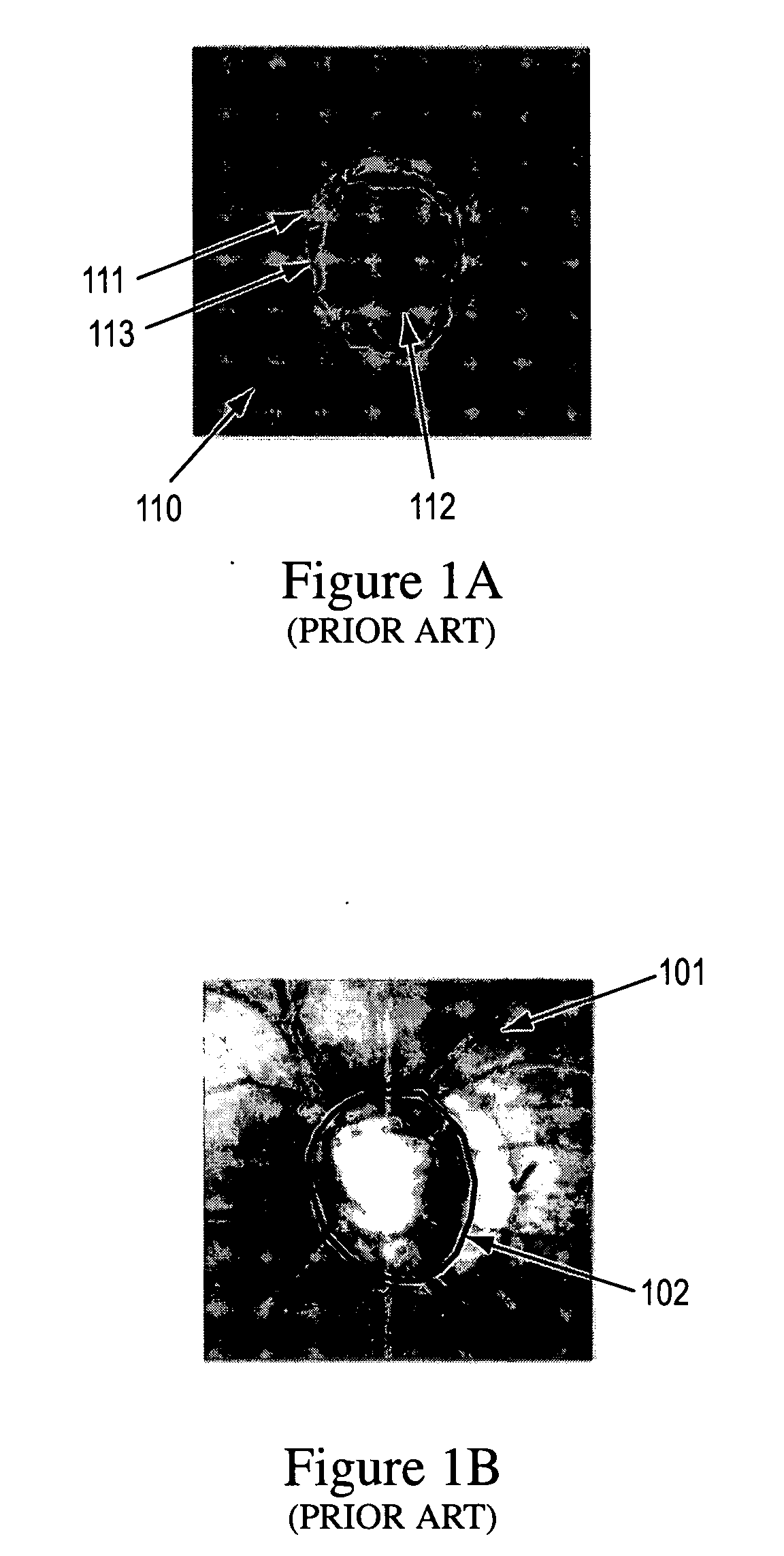
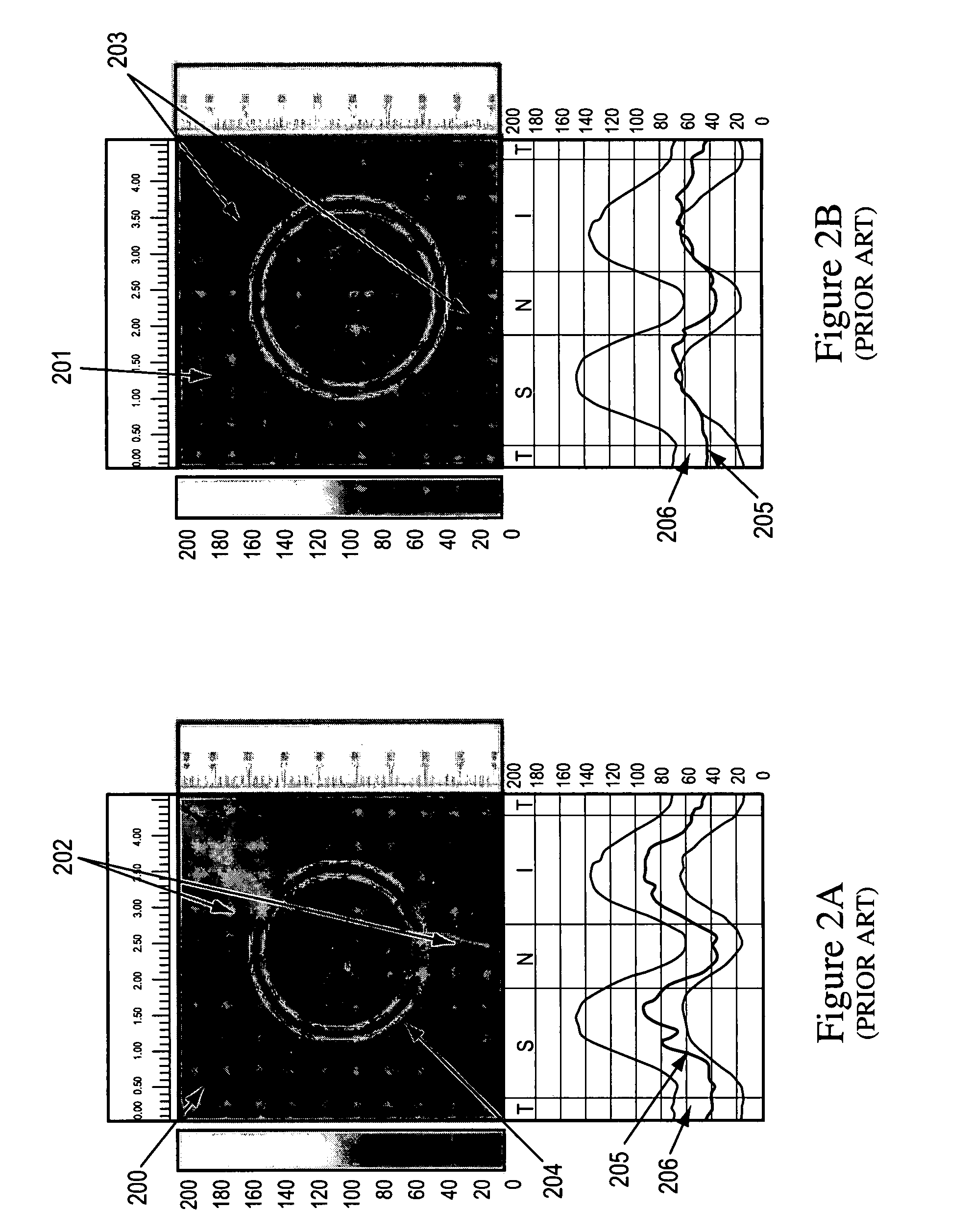
[0030] As discussed above, diagnosis of retinal eye pathologies depends on accurate and complete imaging of the nerve head area. Images of the nerve head area are shown in FIGS. 1A, 1B, 2A, 2B, and 3. FIGS. 1A and 1B were acquired with the HRT technique, FIGS. 2A and 2B were acquired with the GDx Technique, and FIG. 3 was...


PUM


Abstract

A method of performing an OCT image scan is presented. Other images are taken and a template is formed to correct the OCT images, for example, for eye motion, blood vessel placement, and center offset. In some embodiments, video images are taken simultaneously with the OCT images and utilized to correct the OCT images. In some embodiments, a template OCT image is formed prior to acquisition of the OCT images and the template OCT image is utilized as a template from which to correct all of the OCT images.

Description

RELATED APPLICATION [0001] The present application claims priority to Provisional Application No. 60 / 760,046, filed on Jan. 19, 2006, by Jay Wei, Ben Jang, and David Huang, and to Provisional Application No. 60 / 782,888, filed on Mar. 17, 2006, by Jay Wei, Ben Jang, David Huang, and Yonghua Zhao, each of which are herein incorporated by reference in their entirety.BACKGROUND [0002] 1. Field of the Invention [0003] The present invention is related to a method of performing an eye examination utilizing optical coherence tomography (OCT). [0004] 2. Discussion of Related Art [0005] Retinal imaging by conventional optical image methodology, such as fundus camera imaging and indirect ophthalmoscopic imaging, has been routinely used clinically to evaluate retinal structure change. Routine retinal imaging provides valuable information for a clinician to diagnosis a number of eye diseases, including glaucoma. When there is a need to evaluate the optic nerve head tissue structure changes for g...

Claims


Application Information

Patent Timeline
23 Aug 2007
Publication
US20070195269A1
IPC
A61B3/10
CPC
A61B3/102; A61B3/113; G06T2207/30041; G06T2207/10101; G06T2207/20128; G06T7/0081; G06T7/11
Inventors
WEI, JAY; JANG, BEN