

Dc-dc converter
a dc-dc converter and synchronous technology, applied in the direction of electric variable regulation, process and machine control, instruments, etc., can solve the problems of extreme step-up operation from the output side to the input side not being performed, the overvoltage protection circuit can malfunction, and the dc-dc converter can be destroyed, so as to prevent the fluctuation of the output voltage, prevent the rise of the voltage, and prevent the drop of the output voltage
- Summary
- Abstract
- Description
- Claims
- Application Information
AI Technical Summary
Benefits of technology
Problems solved by technology
Method used
Image

Examples
first embodiment
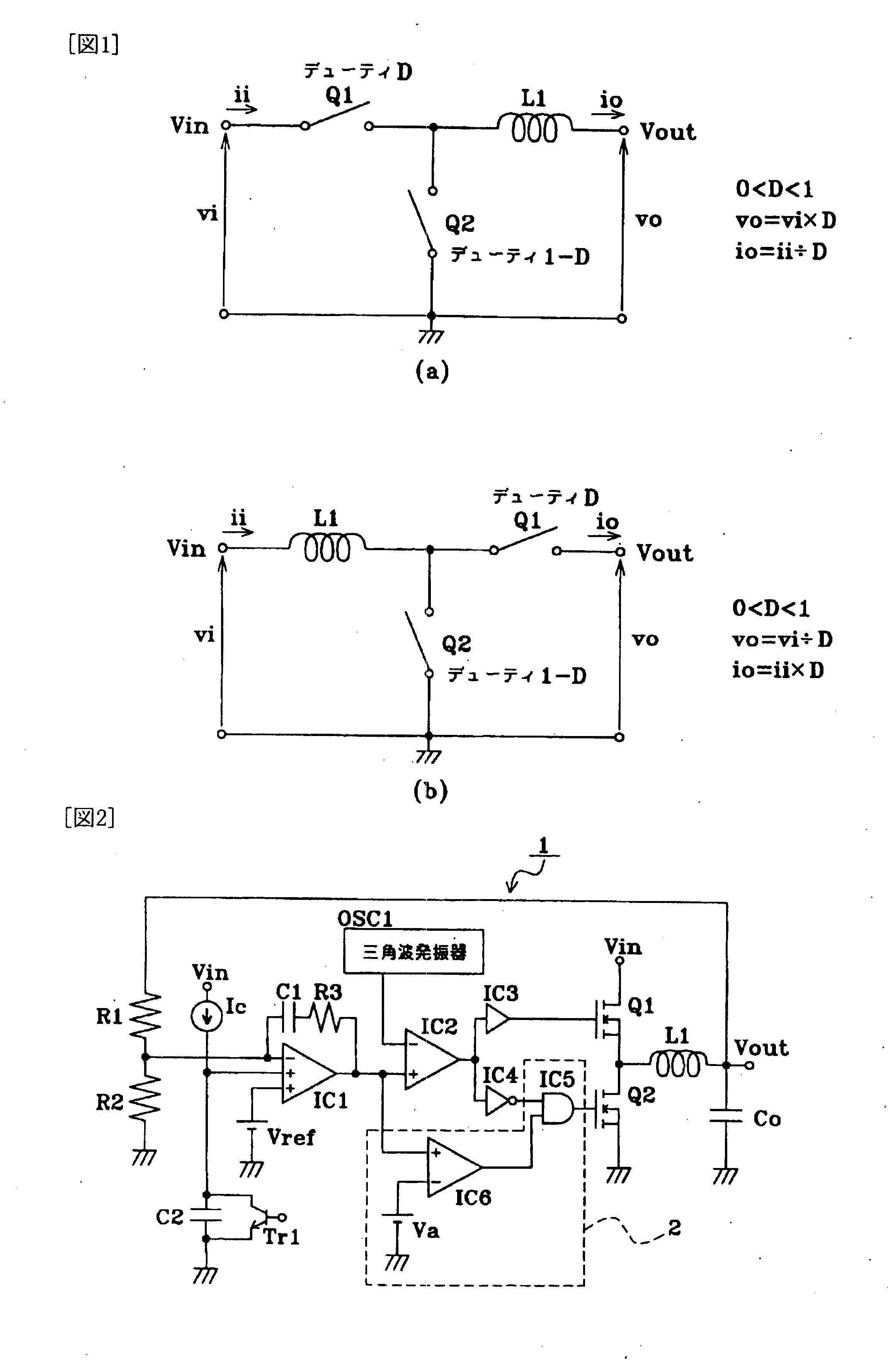
[0038] FIG. 2 is a circuit diagram of a DC-DC converter according to an embodiment of the present invention. In FIG. 2, the DC-DC converter 1 includes, as a basic configuration, a FET Q1 serving as a main switching element, a FET Q2 serving as a synchronous rectifying switching element, a choke coil L1, a smoothing capacitor Co, a three-input error amplifier IC1, and a triangular-wave oscillator OSC1 that is typical as an oscillator for a PWM control circuit.
[0039] A drain of the FET Q1 connects to a voltage input terminal Vin and a source thereof connects to a voltage output terminal Vout via the choke coil L1. A drain of the FET Q2 connects to a node between the FET Q1 and the choke coil L1 and a source thereof is grounded. The smoothing capacitor Co is connected between the voltage output terminal Vout and ground.
[0040] The error amplifier IC1 is supplied with power between the voltage input terminal Vin and the ground so as to operate by a single power supply. A feedback circu...
second embodiment
[0070] In the DC-DC converter 1 according to the first embodiment, a case where a large load current suddenly becomes small during a normal operation is reconsidered. In this case, the output voltage vo tries to rise, and thus the output voltage of the error amplifier IC1 drops accordingly. Although not described in the first embodiment, the output of the error amplifier IC1 may be below the reference voltage va if fluctuation of the load current is too significant. In this case, the ON duty ratio of the FET Q1 becomes zero, but the FET Q2 is turned OFF because the regeneration preventing circuit 2 functions in the DC-DC converter 1. In this case, no current is absorbed from the output side by the FET Q2, which can cause a problem that the risen output voltage does not easily drop. This is because the regeneration preventing circuit 2 can function under some conditions even in the normal operation state.
[0071] FIG. 5 is a circuit diagram of a DC-DC converter according to another em...
PUM
 Abstract
Description
Claims
Application Information