Positioning of a path searcher window in a cdma receiver

Inactive Publication Date: 2007-08-23
TELEFON AB LM ERICSSON (PUBL)
View PDF3 Cites 20 Cited by
  • Summary
  • Abstract
  • Description
  • Claims
  • Application Information

AI Technical Summary

Benefits of technology

[0030] Alternatively, the receiver may further be adapted to compare the signal strength indicator calculated for that known channel to the signal strength indicator calculated for the transposed window, and replace, if the signal strength indicator calculated for the transposed window is larger than the signal strength indicator calculated for that known channel multiplied by a factor, the signal strength indicator for that known channel by the signal strength indicator for the transposed window. This ensures that the receiver can select the optimal value of the signal strength indicator, also in the case where the transposed window does not provide a better value. When the factor equals one, the larger of the two signal strength indicators can be selected. When the receiver is further adapted

Problems solved by technology

These different portions of the signal are a cause of interference in the receiver.
The effect of the combining depends on the instantaneous relationship of the carrier wavelength and distance differences, and it may thus for a given multipath component be either enhancing or destructive.
In case of destructive interference, the combining leads to significant decrease of the magnitude, or fading, of the path gain for that path.
Furthermore, the timing of the demodulation must be synchronized, i.e. the despreading code must be applied to the received signal at the correct instant in time, which can be difficult due to the multipath effects mentioned above.
Due to relative movement of the transmitter, the receiver and the objects in their vicinity, the delays of existing paths change, old paths disappear and new paths appear.
In addition, the frequency offset between the transmitter and receiver circuits gives rise to a slow clock drift, which manifests itself as a gradual movement of the whole delay profile along the time axis.
There is no guarantee th

Method used


Image

  • Positioning of a path searcher window in a cdma receiver
  • Positioning of a path searcher window in a cdma receiver
  • Positioning of a path searcher window in a cdma receiver

Examples


Embodiment Construction

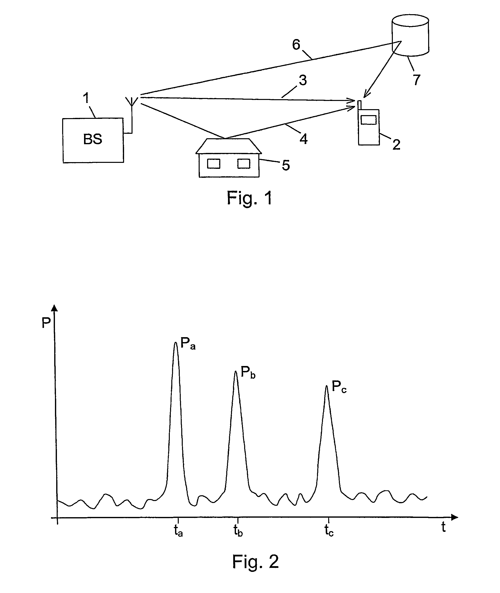
[0047]FIG. 1 shows a situation in which a base station 1 and a mobile station 2 of a wireless communications system communicate with each other. As an example, a signal transmitted from the base station 1 is received by the mobile station 2. However, the transmitted signal travels along multiple paths from the base station to the mobile station. In this case there is a direct and unobstructed propagation path 3, but in addition to this direct path, reflections from objects in the surroundings cause a number of indirect paths to exist. Two such paths are shown in the figure. One indirect path 4 is reflected from a house 5, while another path 6 is caused by reflection from another building 7.

[0048] Since the part of a signal transmitted via one of the indirect paths 4 and 6 has to travel a longer distance to arrive at the mobile station 2, compared to the part of the signal travelling via the direct path 3, multiple instances of the same signal will be received by the mobile station ...


PUM


Abstract

Multipath components of signals transmitted through time-varying digital radio channels are received with individual delays, and signals through a given channel comprise a code identifying that channel. A delay profile indicating a magnitude (Y) for delay values in a search window is calculated repetitively for known channels; the delays of multipath components for known channels estimated; a signal strength indicator calculated; and a search for new multipath components not already estimated performed at regular time intervals. When a new multipath component is found, its identification code is compared to the codes of the known channels. If the code of the new component is identical to the code of a known channel, a delay profile and a signal strength indicator is calculated for a window transposed to include the new multipath component. In this way as many multipath components as possible are included in the search window for a new cell.

Description

TECHNICAL FIELD OF THE INVENTION [0001] The invention relates to a method of detecting multipath components in time-varying fading radio channels in a digital wireless communications system in which individual multipath components of a signal transmitted through a channel are received with individual delays within a range of possible delay values, and in which signals transmitted through a given channel comprise an identification code identifying that channel. The method comprises the steps of calculating repetitively for each of a number of known channels a delay profile indicating a magnitude for each of a number of individual delay values in a search window constituting a subset of said range of possible delay values and being positioned based on at least one previously calculated delay profile for the corresponding channel; estimating from said delay profiles the delays of multipath components for each known channel; calculating from said delay profiles a signal strength indicat...

Claims


Application Information

Patent Timeline
IPC IPC(8): H04B1/00H04B1/707
CPCH04B1/70735H04B1/70754H04B2201/70702H04B1/7117H04B1/7113
Inventor JONSSON, ELIASPERSSON, ROGER
Owner TELEFON AB LM ERICSSON (PUBL)
Why Eureka
Try Eureka