Process for removing sulfur particles from an aqueous catalyst solution and for removing hydrogen sulfide and recovering sulfur from a gas stream

a technology of aqueous catalyst and sulfur particles, which is applied in the direction of sulfur preparation/purification, physical/chemical process catalysts, separation processes, etc., can solve the problems of contactor clogging, affecting the operation of the contactor, and ultimately flooding, so as to achieve reliable and economical

Inactive Publication Date: 2007-08-23
RES INST OF PETROLEUM IND RIPI
View PDF13 Cites 8 Cited by
  • Summary
  • Abstract
  • Description
  • Claims
  • Application Information

AI Technical Summary

Benefits of technology

[0012] It is an object of the present invention to provide a more efficient, reliable and economical process for removing hydrogen sulfide and recovering sulfur from a gas stream. According to another aspect of the invention excessive foaming and flooding of the oxidizer zone is to be avoided in such a process. It is another object of the present invention to provide a more efficient, reliable and economical process for removing sulfur particles from an aqueous catalyst solution used to remove hydrogen sulfide from a gas stream.

Problems solved by technology

The presence of hydrogen sulfide in gas streams causes different problems in oil, gas and petrochemical industries and even wood and drink industries.
This is mainly because of the poisonous and corrosive effects of H2S.
Due to settling or sedimentation of sulfur particles, however, the contactor can become plugged.
If the settling happens to a great extent and the tower is plugged, this will perturb the contactor, in particular an absorber, and it will ultimately flood.
Often, such a packing does not exhibit optimum reaction rates.

Method used


Image

  • Process for removing sulfur particles from an aqueous catalyst solution and for removing hydrogen sulfide and recovering sulfur from a gas stream
  • Process for removing sulfur particles from an aqueous catalyst solution and for removing hydrogen sulfide and recovering sulfur from a gas stream
  • Process for removing sulfur particles from an aqueous catalyst solution and for removing hydrogen sulfide and recovering sulfur from a gas stream

Examples


Embodiment Construction

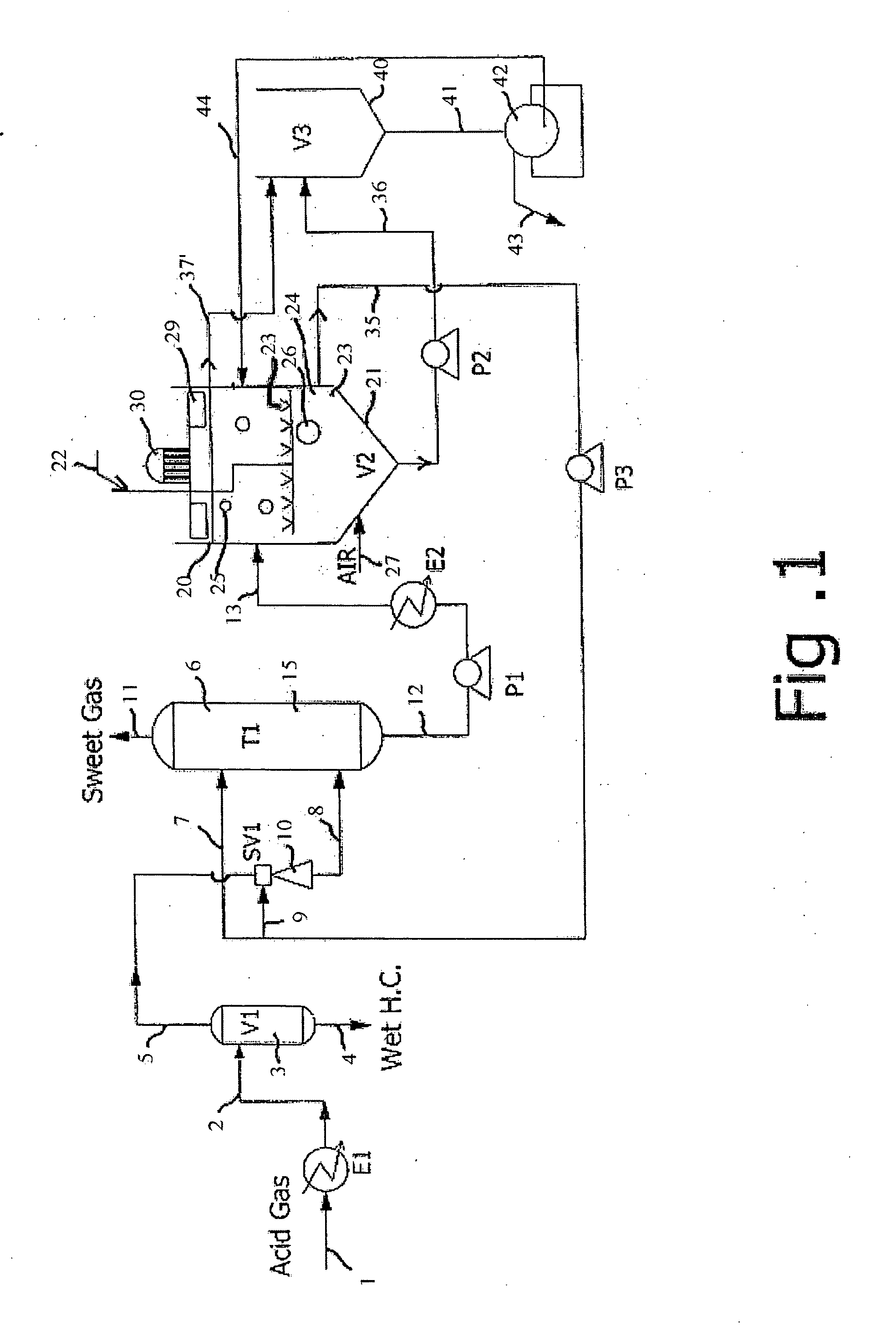
[0041] The present invention relates to the reduction of foaming and plugging in processes where H2S is separated from H2S-containing gas streams, by being contacted with an aqueous catalyst solution comprising a chelate of a polyvalent metal ion, which is preferably an iron chelate.

[0042] As shown in FIG. 1, the overall process comprises three major sections, namely the contact zone 6, the oxidizer zone 20 and the separator zone 40. As shown in FIG. 1, a sour or acid gas 1 is fed via a heat exchanger E1 and line 2 to a gas-liquid-separator 3, which separates any liquid heavy hydrocarbons and water to line 4, as outlined further below. The separated gaseous hydrocarbons are fed via line 5, Venturi scrubber 10 and line 8 to the contact zone 6. More specifically, the acid or sour gas stream 8 enters the contact zone 6 at a bottom part thereof.

[0043] The contact zone 6 can be an absorber, a static mixer, a Venturi scrubber or a combination thereof. Preferably, according to the presen...


PUM

PropertyMeasurementUnit
timeaaaaaaaaaa
temperatureaaaaaaaaaa

Abstract

The invention relates to a process for removing hydrogen sulfide and recovering sulfur from a gas stream, comprising the steps of: contacting said gas stream with an aqueous catalyst solution of a polyvalent metal redox catalyst in a contacting zone to absorb said hydrogen sulfide and form a reduced catalyst solution comprising reduced polyvalent metal redox catalyst and sulfur particles; oxidizing said reduced catalyst solution while removing sulfur particles to form said oxidized aqueous catalyst solution comprising polyvalent metal redox catalyst in an oxidized state with sulfur particles removed; and recovering sulfur by transferring at least one of said sulfur particles and foam to a separation zone; wherein a coagulating reagent is added to a feed of said separation zone prior to entering said separation zone to promote settlement of sulfur particles.

Description

CROSS-REFERENCE TO RELATED APPLICATION [0001] The present application is a divisional application from U.S. patent application Ser. No. 11 / 446,021 with the title ‘A process for removing sulfur particles from an aqueous catalyst solution and for removing hydrogen sulfide and recovering sulfur from a gas stream’ filed on Jun. 1, 2006, which claims priority from European patent application no. 05104812.2 with the title ‘A process for removing sulfur particles from an aqueous catalyst solution and for removing hydrogen sulfide and recovering sulfur from a gas stream’ filed on Jun. 2, 2005, the whole content of which is hereby incorporated by reference.TECHNICAL FIELD OF THE INVENTION [0002] The present invention relates to a process for removing hydrogen sulfide (H2S) from gas streams, by using a redox process and removing the resulting sulfur particles from an aqueous catalyst solution used during the redox process. BACKGROUND OF THE INVENTION [0003] The presence of hydrogen sulfide in...

Claims


Application Information

Patent Timeline
Patent Type & Authority Applications(United States)
IPC IPC(8): B01D53/14
CPCB01D53/8612B01J31/4015B01J31/403B01J38/70B01J2531/842C01B17/0205C02F2303/12C02F1/24C02F1/54C02F1/72C02F2101/101C02F2103/18C02F2301/022C01B17/05Y02P20/584
Inventor KHATTATY, MOHAMMAD REZAFORSAT, KHALEDHASHEMI, REZAHOSSEIN, MANAFI VARKIANI
Owner RES INST OF PETROLEUM IND RIPI
Why Eureka
Try Eureka