
Laminate panel and process for production thereof

a technology of laminate panels and resins, applied in the field of laminate panels, can solve the problems of less than desirable weight and cost of laminate products incorporating such polymer core materials, and the resin used in laminates may have a softening point, and achieve the effect of facilitating the production of parts

Inactive Publication Date: 2007-08-23
DOFASCO INC
View PDF3 Cites 36 Cited by
  • Summary
  • Abstract
  • Description
  • Claims
  • Application Information

AI Technical Summary

Benefits of technology

[0016] It is another object of the present invention to provide a laminate panel capable of withstanding the conditions of paint / bake cycles to which vehicular panels are conventionally subjected.
[0017] It is another object of the present invention to provide a laminate panel having desirable properties (e.g., impact load or impact resistance) for use in a vehicular application.
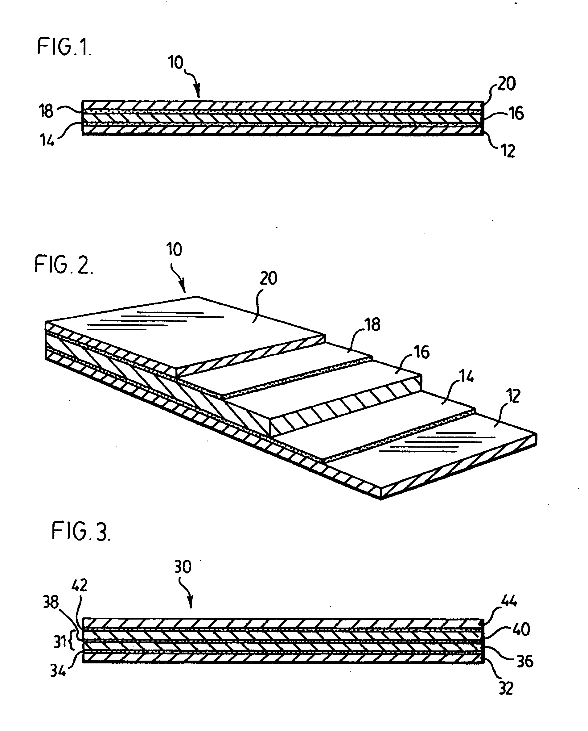
[0025] Thus, the present inventors have discovered a laminate material consisting of a novel combination of a porous layer and thermoplastic resin that can withstand the paint / bake cycles referred to above while maintaining a desirable balance of physical properties (e.g., peel strength, stiffness, impact resistance and the like). Another distinct advantage of the present laminate panel is its formability. This allows for the use medium or deep draw forming techniques to facilitate production of parts having a variety of shapes and radii (e.g., 90° bends, draws, stretches, multi-shape configurations and the like) for vehicular applications.

Problems solved by technology

Increasing sheet steel thickness, however, produces a panel that is not only heavier, but also more expensive.
The weight and cost of laminate products incorporating such polymer core materials, however, is less than desirable.
However, if a composite material, such as that described in Clifford #1 and Clifford #2 is used, there is a risk that the resin used in the laminate may have a softening point near or a melting point below the baking temperature referred to above.

Method used


Image

  • Laminate panel and process for production thereof
  • Laminate panel and process for production thereof
  • Laminate panel and process for production thereof

Examples


examples

[0063] In the Examples a number of samples were made using steel skins and a core.

[0064] Each steel skin had a thickness of 0.010 inches and a zinc coating (˜60 g / m2) on each side.

[0065] The core was either resin alone or a combination of resin and a reinforcing layer.

[0066] The resin was a thermoplastic co polyester based elastomer, where the co polyester is a polyether-ester formulation. The resin was used in sheet form. The thickness used in each sample is reported Table 1.

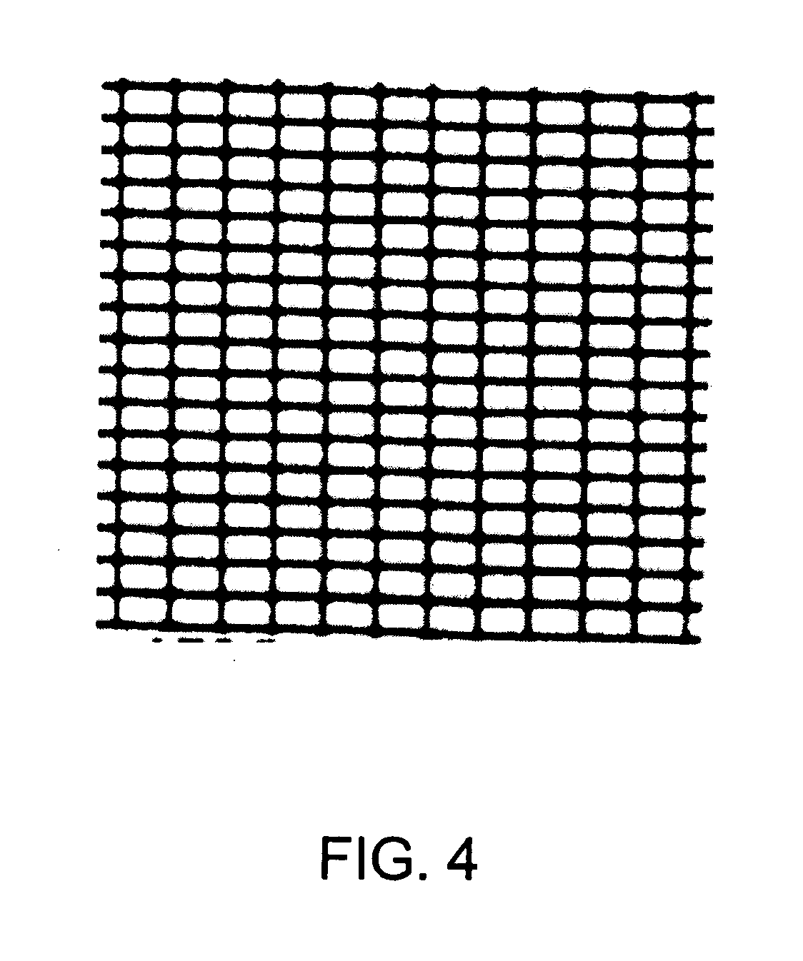
[0067] The reinforcing layers used in the samples were: steel woven mesh, woven jute of different weave types, paper, cotton and linen.

[0068] Various combinations of pressure, temperature and cycle times were investigated.

[0069] The samples were made on a Carver press (75t) at 450° F., for 1 min with a pressure of 10 tons (about 138 psi, except for the resin only samples); followed by a cool in the press, under pressure to 350° F., cooled at about 1.5 s. ° F.−1.

[0070] The samples produced are summarized ...


PUM

PropertyMeasurementUnit
Temperatureaaaaaaaaaa

Abstract

There is disclosed a laminate panel and a process for production thereof. The laminate panel comprises a core layer disposed between and bonded to each of a first metal layer and a second metal layer. The core layer comprises a porous layer substantially encapsulated by a thermoplastic resin. An advantage of the present laminate material is that it can withstand paint / bake cycles while maintaining a desirable balance of physical properties (e.g., peel strength, stiffness, impact resistance and the like). Another distinct advantage of the present laminate panel is its formability. This allows for the use medium or deep draw forming techniques to facilitate production of parts having a variety of shapes and radii (e.g., 90° bends, draws, stretches, multi-shape configurations and the like) for vehicular applications.

Description

CROSS-REFERENCE TO RELATED APPLICATION [0001] The present application claims the benefit under 35 U.S.C. §119(e) of provisional patent application Ser. No. 60 / 627,148, filed Nov. 15, 2004, the contents of which are hereby incorporated by reference.BACKGROUND OF THE INVENTION [0002] 1. Field of the Invention [0003] In one of its aspects, the present invention relates to a laminate panel, more particularly to a metal skinned laminate panel. In yet another of its aspects, the present invention relates to a method for producing a laminate panel. [0004] 2. Description of the Prior Art [0005] Sheet steel is used extensively to form panels. The required structural characteristics, such as stiffness, vary depending upon the specific application. When higher stiffness values are required, the steel thickness is typically increased. Increasing sheet steel thickness, however, produces a panel that is not only heavier, but also more expensive. [0006] A number of approaches have been taken in th...

Claims


Application Information

Patent Timeline
IPC IPC(8): B32B15/14C09J5/06B22F3/10
CPCB22F7/004Y10T428/12042B32B3/266B32B5/18B32B5/32B32B15/046B32B15/08B32B15/085B32B15/09B32B15/14B32B15/18B32B15/20B32B37/12B32B37/1207B32B2250/40B32B2262/06B32B2274/00B32B2305/026B32B2307/102B32B2307/558B32B2307/738B32B2311/00B32B2605/00B32B2605/08B62D29/043B22F2998/00B22F3/002Y10T442/656Y10T442/3415
Inventor BIGGS, TARYNCASTRICIANO, FRANKCHOONOO, KARENGUERRA, GINAHAYES, KEVINWITT, JEFFREY
Owner DOFASCO INC
Learn More