Three dimensional multilayer barrier and method of making

a multi-layer barrier and three-dimensional technology, applied in the direction of cell component details, instruments, transportation and packaging, etc., can solve the problems of compromising the encapsulation, lateral diffusion into the exposed permeable decoupling layer of the multi-layer barrier, and finite lateral diffusion rate of moisture and oxygen

Inactive Publication Date: 2007-08-23
VITEX SYST
View PDF99 Cites 128 Cited by
  • Summary
  • Abstract
  • Description
  • Claims
  • Application Information

AI Technical Summary

Problems solved by technology

Lateral diffusion into the exposed permeable decoupling layers of a multilayer barrier is an issue with respect to use of these structures for encapsulation.
The lateral diffusion rate of moisture and oxygen is finite, and this will eventually compromise the encapsulation.
However, this decreases the area of the substrate which is usable for active envi...

Method used


Image

  • Three dimensional multilayer barrier and method of making
  • Three dimensional multilayer barrier and method of making
  • Three dimensional multilayer barrier and method of making

Examples


Embodiment Construction

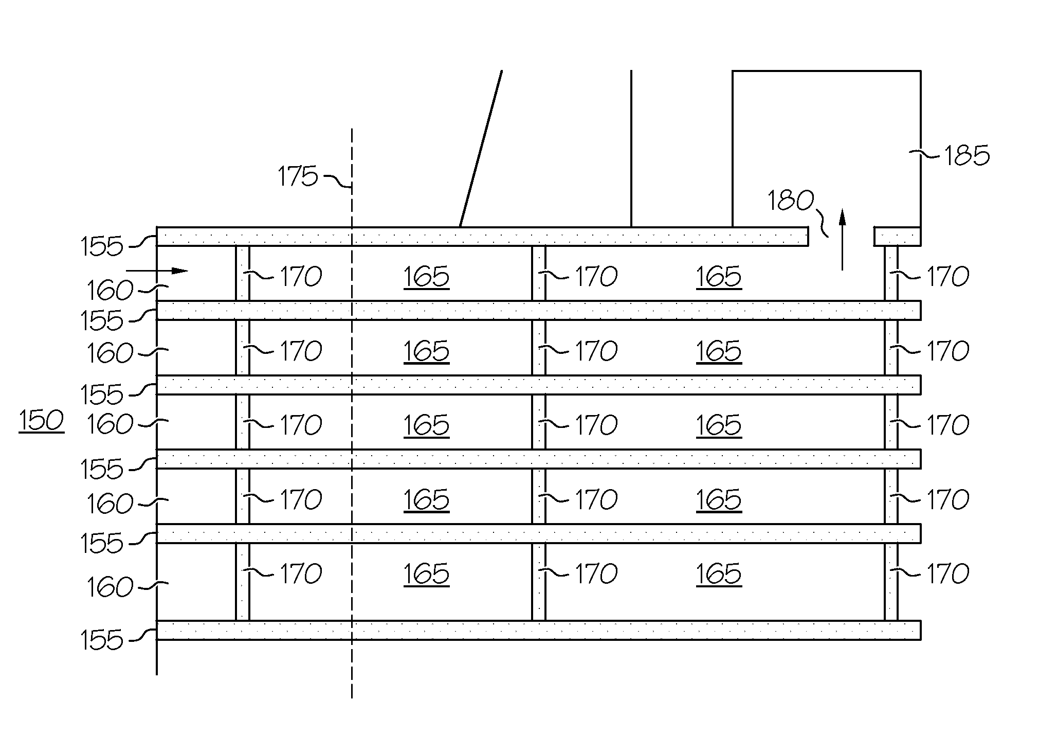
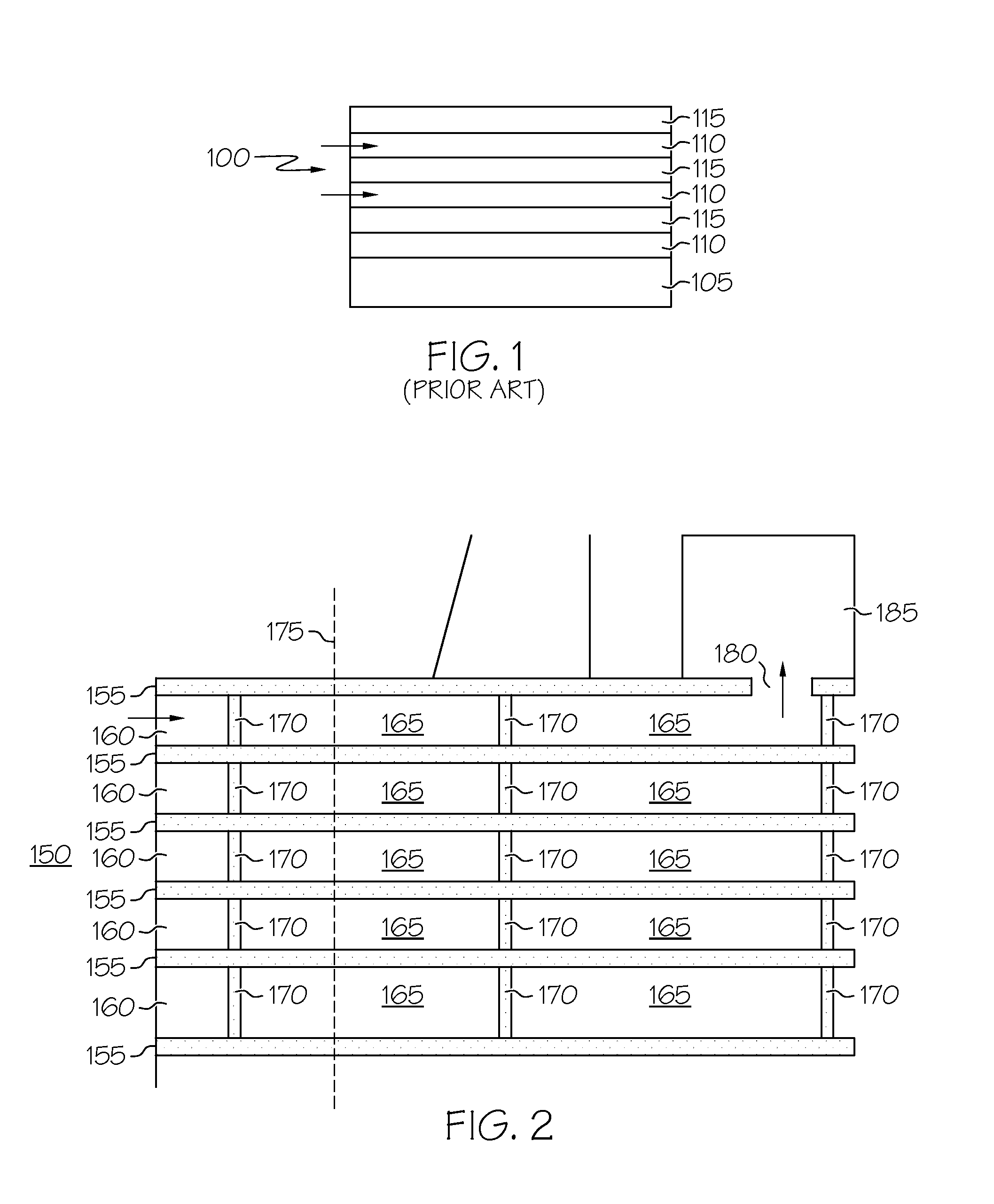
[0024]FIG. 2 illustrates the concept of the three dimensional multilayer barrier 150. There are alternating barrier layers 155 and decoupling layers 160. The decoupling layers 160 have sections 165 separated by walls 170. The walls 170 are made of barrier material. Dotted line 175 indicates where a cut could be made that would still result in a wall between the cut edge and the defect 180 in the barrier layer which would prevent the permeants from diffusing to the environmentally sensitive device 185, causing device failure. The walls can be repeated as often as needed across the decoupling layer so that the three dimensional multilayer barrier can be cut while still providing a wall between the permeants and the device.

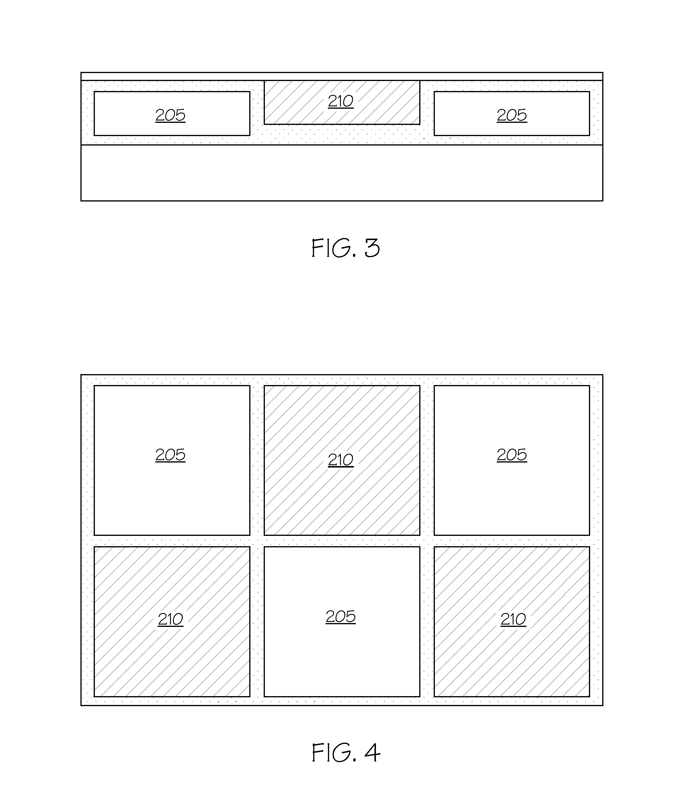
[0025] The three dimensional multilayer barrier shown FIG. 2 is highly simplistic. It depicts simple rectangular cross-sections and perfect staking of cellular decoupling layers. The cells can be polygonal, circular, or other shapes, if desired. The walls do not hav...


PUM

PropertyMeasurementUnit
Speedaaaaaaaaaa
Water vapor transmission rateaaaaaaaaaa
Relative humidityaaaaaaaaaa

Abstract

A three dimensional multilayer barrier. The barrier includes a first barrier continuous layer adjacent to a substrate; a first discontinuous decoupling layer adjacent to the first continuous barrier layer, the first discontinuous decoupling layer having at least two sections; and a second continuous barrier layer adjacent to the first discontinuous decoupling layer, the second barrier forming a wall separating the sections of the first discontinuous decoupling layer. A method of making the three dimensional multilayer barrier is also described.

Description

BACKGROUND OF THE INVENTION [0001] This application is a continuation-in-part of U.S. application Ser. No. 11 / 068,356, filed Feb. 28, 2005, which is a Division of U.S. application Ser. No. 09 / 966,163, filed Sep. 28, 2001, now U.S. Pat. No. 6,866,901, which is a continuation-in-part of U.S. application Ser. No. 09 / 427,138, filed Oct. 25, 1999, now U.S. Pat. No. 6,522,067, all of which are incorporated herein by reference.[0002] Multilayer, thin film barrier composites having alternating layers of barrier material and polymer material are known. For example, U.S. Pat. No. 6,268,695, entitled “Environmental Barrier Material For Organic Light Emitting Device And Method Of Making,” issued Jul. 31, 2001; U.S. Pat. No. 6,522,067, entitled “Environmental Barrier Material For Organic Light Emitting Device And Method Of Making,” issued Feb. 18, 2003; and U.S. Pat. No. 6,570,325, entitled “Environmental Barrier Material For Organic Light Emitting Device And Method Of Making”, issued May 27, 20...

Claims


Application Information

Patent Timeline
IPC IPC(8): B32B15/00B05D1/36B32B7/00C23C16/00B05D3/00G02F1/1333H01L23/00H01L51/52H01M50/186
CPCG02F2001/133337H01L23/562H01L51/5237H01L2924/12044Y10T428/12347H01L2924/0002H01M2/08Y10T428/24H01L2924/00Y02E60/10G02F1/133337H01M50/186H10K50/8445
Inventor VISSER, ROBERT JANMORO, LORENZABURROWS, PAUL E.MAST, ERIC S.MARTIN, PETER M.GRAFF, GORDON L.GROSS, MARK E.BONHAM, CHARLES C.BENNETT, WENDY D.HALL, MICHAEL G.
Owner VITEX SYST
Why Eureka
Try Eureka