Biometric verification and duress detection system and method

a biometric verification and duress detection technology, applied in the field of security systems and biometric identification systems, can solve the problems of wireless tags providing significant security breaches, insufficient by themselves to ensure adequate security, and voice or other biometric authentication technologies,

Active Publication Date: 2007-08-23
ADEMCO INC
View PDF17 Cites 139 Cited by
  • Summary
  • Abstract
  • Description
  • Claims
  • Application Information

AI Technical Summary

Benefits of technology

[0008] The present invention addresses the above identified problems, potential security breach and other issues by providing a security system wherein the user is provided with dual layered verification system in addition to an unique identifier given to the user. In particular, the user is either given a wireless tag with a unique identifier or a unique passcode that is entered into the security system for identification. The present invention relates to a system and method for providing a biometric authenticated entry and e...

Problems solved by technology

However, the above-mentioned technologies, even though implemented to simplify the operations of security systems, have several performance disadvantages.
For example, voice or other biometric authentication technologies, while presenting a simple user interface for the activation and deactivation of a security system, may not be sufficient by themselves to ensure adequate security.
However, wireless...

Method used


Image

  • Biometric verification and duress detection system and method
  • Biometric verification and duress detection system and method
  • Biometric verification and duress detection system and method

Examples


second embodiment

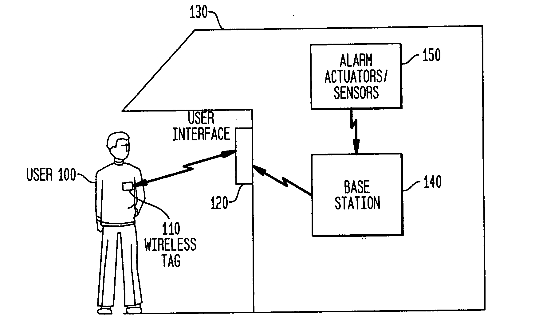
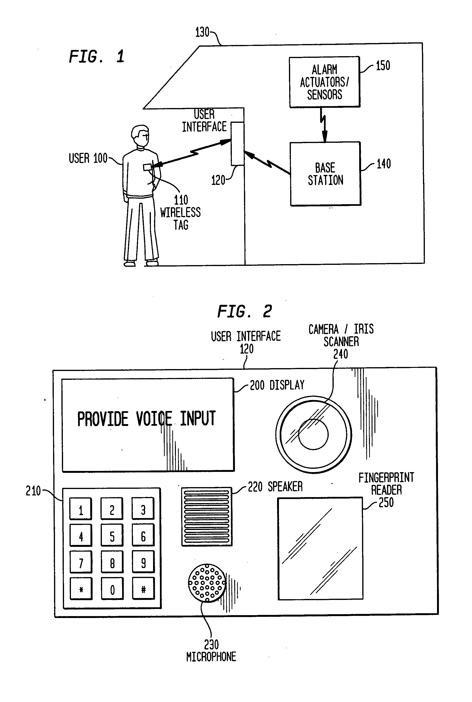
[0051] The biometric user interface and base station, according to the invention, is not only used to verify the identity of an user, but also to determine whether the user is being forced to disarm the base station by an intruder. In other words, the biometric user interface and base station is used to detect if the user is under duress.

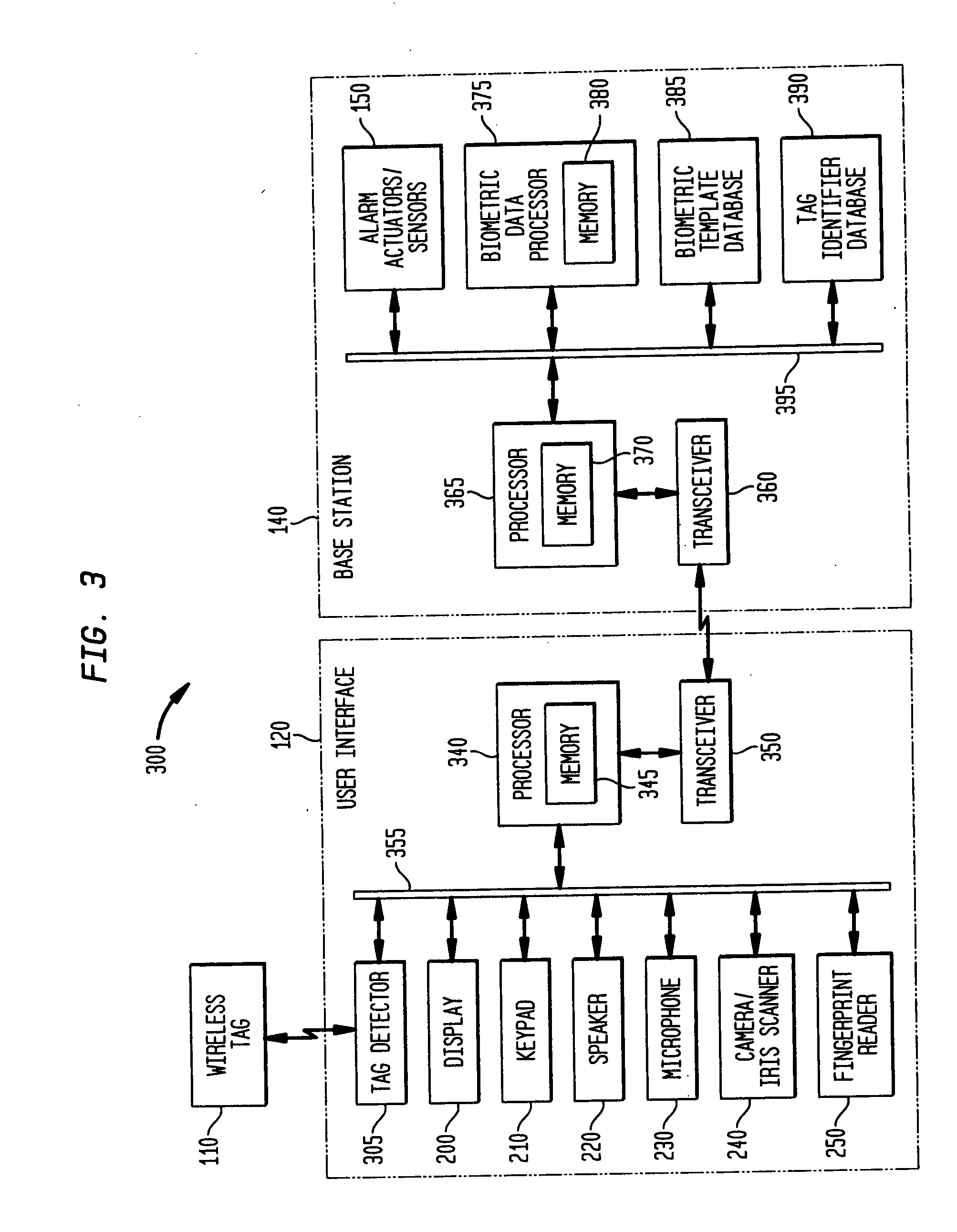
[0052] The user interface 705 in the second embodiment includes a first identification device 715 for receiving a unique identifier associated with a particular user. The unique identifier can be unique wireless tag or access card with an identifier stored or written on the tag. Additionally, the unique identifier can simply be a unique passcode assigned to a particular user. If the unique identifier is a wireless tag or access card, the first identification device 715 communicates with the wireless tag 110 that is carried by the user. The first identification device 715 can actively interrogate the wireless tag, if the tag is passive. Optionally, t...

first embodiment

[0054] The base station 710 includes a processor, e.g., control 365 with memory 370 for controlling the overall functioning of the base station 710, as well as the communication of data with the user interface 705 via a transceiver 360. Although not depicted, the base station can include similar alarm actuators / sensors 150 as the base station of the invention. The base station 710 includes biometric data processor 375, including memory 380, a biometric template database 385, duress indicator database 730 and an identifier database 740. In one possible configuration the biometric data processor 375, a biometric template database 385, duress indicator database 730 and an identifier database 740 communicate with the processor 365 via a bus 395. The term “database” is meant to encompass any type of data storage resource, regardless of how configured or organized. Additionally, while the three databases, biometric, duress and identifier have been depicted as being separate databases, one...

third embodiment

[0074] The system according to the invention is similar to the system illustrated in FIG. 7, except the processor 365 includes a timer and that is a threshold database.

[0075] In another embodiment, a combination of the second and third embodiments can be used to verify a user and confirm that a user is not under duress. In this embodiment, both a time threshold and a duress indicator are used. A silent alarm signal is transmitted to a central monitoring station if a timer expires prior to any input to the second identification device 720 or if the user inputs the duress indicator into the second identification device 720. The timer is initially set when the first identification device 715 detects a first input. The timer is set to a time threshold corresponding to the detected identifier, detected by the first identification device 715 and determined by the processor 365.


PUM


Abstract

A multi-stage verification system including a first and second identification device to verify the identity of the user and to determine if the user is under duress. When a user approaches an entrance to a building, a first identifier is detected by the first identification device, the identifier is compared to a pre-stored identifier. If there is a match, the user inputs at least one biometric input into the second identification device. The biometric input is compares with pre-stored information in two different databases, a biometric template database and a duress indicator database. If there is a match with the duress indicator database, a silent alarm signal is transmitted to a central monitoring station and the security system is disarmed. If there is a match with the biometric template database, the security system is controlled in the intended manner.

Description

RELATED APPLICATION [0001] This application is a continuation-in-part of U.S. patent application Ser. No. 10 / 970,198 filed on Oct. 21, 2004 entitled “Voice Authenticated Alarm Exit and Entry System”, and assigned to Honeywell International, Inc.BACKGROUND OF THE INVENTION [0002] 1. Field of Invention [0003] The present invention relates generally to the field of security systems and biometric identification system. Further, the present invention relates to security systems that use biometric activation technology to aid in the secure activation and deactivation of the security system. [0004] 2. Description of Related Art [0005] Currently available wireless security systems for commercial or home use typically include a hardwired or wireless keypad, an alarm base station and an alarm siren in addition to various additional optional hardware features. Due to the increasing complexity of security systems, a need has arisen to simplify the efforts a human user has to employ in order to ...

Claims


Application Information

Patent Timeline
IPC IPC(8): H04K1/00
CPCG07C9/00087G08B25/008G07C2209/04G07C9/257
Inventor MARTIN, CHRISTOPHER D.OH, ERICADDY, KENNETH L.ESKILDSEN, KENNETH G.
Owner ADEMCO INC
Why Eureka
Try Eureka