
Liquid-solids applicator with valve means to permit cleaning

Inactive Publication Date: 2007-08-30
SALFORD GRP INC
View PDF3 Cites 12 Cited by
  • Summary
  • Abstract
  • Description
  • Claims
  • Application Information

AI Technical Summary

Benefits of technology

[0017] The present invention thus relates to an apparatus adapted for providing liquids or liquid—solid dispersions to soil, which in one embodiment, by virtue of its structure and arrangement of valve means, permits not only passage of a pig member therethrough for cleaning purposes which apparatus can thereafter, with little effort save manipulation of various switches from the cab of a tractor, commence operation, but further permits initially-supplied liquid solid dispersions to be ejected from the apparatus so as to thereby avoid initial plugging of the supply tubes which typically occurs during start-up due to the above-described dehydration phenomenon. Alternatively, such apparatus is adapted to allow, immediately after application of a liquid or solid-liquid dispersion to soil, cleaning thereof with mere manipulation of a valve from the cab of a tractor towing such apparatus.
[0018] The apparatus of the present invention in a preferred embodiment may also possess second valve means. In the embodiment of the invention wherein second valve means are provided, such not only prevents such liquid-solid dispersion from flowing to the manifold of the apparatus during a cleaning step, but further operates to prevent siphoning in situations where siphoning may occur and thus prevent unwanted application of liquid-solid dispersions by the apparatus at times when not desired.
[0019] Accordingly, the applicator apparatus of the present invention, in its various embodiments, which may each exist in the apparatus individually or may all be combined in a single apparatus, permits both cleaning of the apparatus by a pig member at the same time as cleaning of the supply hose, permits ejection of initial fibrous masses during initial start-up, prevents unintended siphoning, and may further be configured so as to best permit drainage of the apparatus after use.

Problems solved by technology

Problematically, however, the supply hose is typically initially in a dry condition and contains only air.
Thus the initial portion of the liquid-solid dispersion which is pumped to the applicator apparatus will typically arrive at the apparatus in a dehydrated condition bereft of most liquid and moisture therein and thus as a fibrous solid mass, which typically results in initial plugging of the apparatus, particularly at the manifold and supply tubes, where the individual supply tubes, due to their smaller diameter relative to the diameter of the supply hose, are much more susceptible to plugging.
Also problematically, liquid- solid dispersions which may have remained in the apparatus from a period of previous use (particularly where the apparatus is not configured to allow proper draining) will typically have lost a substantial portion of the liquid in such liquid- solid dispersion due to evaporation, leaving a fibrous solid material in the apparatus which need first be removed or cleaned from the apparatus before operation can be renewed.
Such results in a restriction of the effective interior diameter through which such liquid-solid slurry need be pumped.
In cases where non-fabric supply hose is used, which in contrast to flexible fabric hoses may be subject to a vacuum pressure, and where the applicator apparatus is at an elevation below that of the supply lagoon, undesirably even after cessation of the operation of the supply pump, liquid-solid dispersions may still continue to flow to the applicator apparatus due to the siphoning effect.
Thus undesirably in such circumstances, even though an operator of a applicator apparatus may stop the apparatus in the field, supply of such liquid-solid dispersion to the applicator apparatus will continue due to the siphoning effect.

Method used


Image

  • Liquid-solids applicator with valve means to permit cleaning
  • Liquid-solids applicator with valve means to permit cleaning
  • Liquid-solids applicator with valve means to permit cleaning

Examples


Embodiment Construction

[0079] In all figures, for consistency, identical components are identified with identical reference numerals.

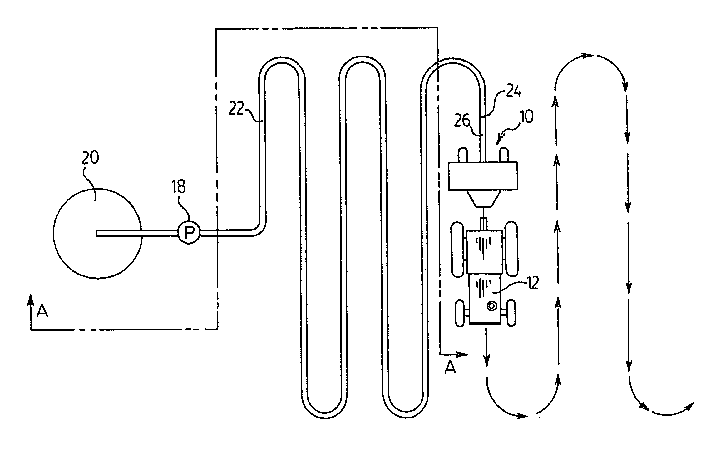
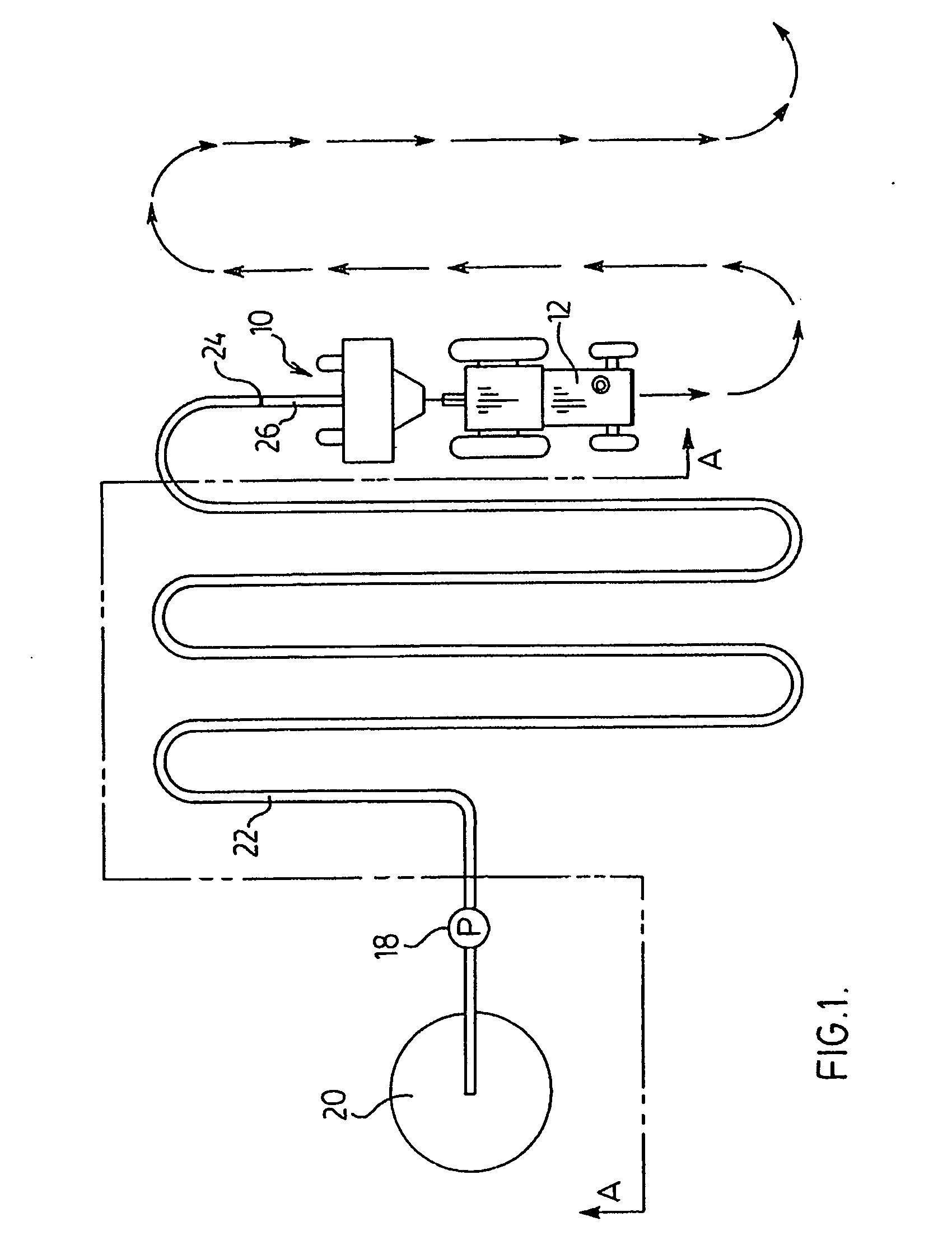
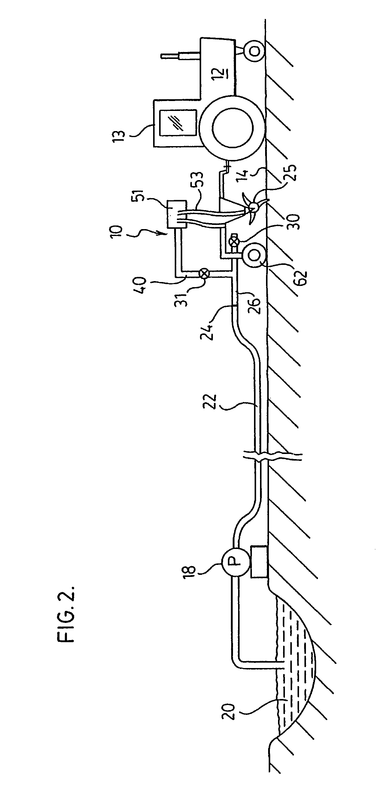
[0080]FIGS. 1-3 show an applicator apparatus 10 of the present invention, adapted to be towed by a tractor 12 over land 14 to which a liquid or liquid solid dispersion is desired to be applied.

[0081] As seen from FIGS. 1-3, a liquid or liquid solid dispersion 16, typically contained in a lagoon 20, may be pumped via pump 18 into a flexible supply hose 22, typically of pvc plastic or woven fabric.

[0082] Such supply hose 22 is releasibly connected to applicator apparatus 10 via a releasable fluid coupling 24. Such releasable coupling may be any of the type common in the art.

[0083] In practice, applicator apparatus 10 is typically towed in serpentine fashion over land 14 to consistently apply the liquid or liquid solid dispersion to the tract of land 14.

[0084] Alternatively, the source of liquid solid dispersion, instead of being a storage lagoon 20, may be an elevated tan...


PUM


Abstract

Apparatus for applying liquid-solid dispersions to soil. Valve means are provided which permit cleaning. An elongate conduit, with an aperture at one end, and a first valve proximate such aperture may be opened to permit passage of a pig member. An upwardly extending conduit is “T'ed” off the elongate conduit, and connects with a manifold and a plurality of supply tubes to direct the liquid-solid dispersions to the soil at various points along the frame of the applicator. A second valve may be provided on the upwardly extending conduit, which may be closed to prevent initial supply of the liquid-solid dispersion to the apparatus and instead flow to the aperture to prevent plugging during initial operation. The second valve, when closed, further serves as an anti-siphoning valve to prohibit further supply of liquid solid dispersion to the manifold. A method for cleaning such apparatus is further disclosed.

Description

FIELD OF THE INVENTION [0001] This invention relates to farm equipment, and in particular to an apparatus adapted for applying liquids or liquid-solid dispersions, such as liquid manure, to soil. BACKGROUND OF THE INVENTION AND DESCRIPTION OF THE PRIOR ART [0002] Various liquid or liquid solid dispersions, such as liquid manure from feedlot operations, milk by-products and wastes from dairy operations, biodegradable wastes from food processing plants, municipal bio-solids from sewage treatment plants, or commercially-available liquid fertilizers, are all valuable sources of nutrients for agricultural crops. [0003] A number of prior art agricultural implements, such as the Aerway™ SSD* implement manufactured by Holland Equipment Ltd. of Norwich, Ontario Canada, exist for applying such liquid-solid dispersions to tracts of land to provide such valuable nutrients thereto. Trade Mark of Holland Equipment Ltd., Norwich, Ontario [0004] A dragline system is typically employed to provide th...

Claims


Application Information

Patent Timeline
IPC IPC(8): A01C23/00
CPCA01C23/001A01C23/008A01C23/005Y10S111/90
Inventor MCLEOD, ROBERT ARCHIE
Owner SALFORD GRP INC
Learn More