Control method for fuel cell vehicle, and fuel cell vehicle

a fuel cell and control method technology, applied in the direction of battery/fuel cell control arrangement, cell components, instruments, etc., can solve the problems of difficult to secure desired output power, difficult to appropriately change the ratio between the output power input from the fuel cell into the converter of the power converter, and the output power input from the secondary battery into, so as to prevent problems such as deterioration of the power storage device

Inactive Publication Date: 2007-08-30
HONDA MOTOR CO LTD
View PDF3 Cites 29 Cited by
  • Summary
  • Abstract
  • Description
  • Claims
  • Application Information

AI Technical Summary

Benefits of technology

[0012] According to the control method for a fuel cell vehicle, when the remaining capacity of the power storage device is determined to be equal to or less than the predetermined remaining capacity threshold value, by controlling an operation of the first DC-DC converter such that the output electrical power of the power storage device becomes equal to or less than the predetermined electrical power threshold value, it is possible to prevent problems such as deterioration of the

Problems solved by technology

In the above-mentioned conventional power controller, since the output voltage of the fuel cell and the discharged voltage of the secondary battery which was converted so as to be substantially equivalent to the output voltage of the fuel cell are input into the converter of the power converter, it was impossible to appropriately change the ratio between the output power input from the fuel cell into the converter of the power converter, and the output power input from the secondary battery into the converter of the power converter.
Therefore, it was difficult to secure desired output power, while, for example, protecting the fuel cell and the secondary battery in accordance with operation

Method used


Image

  • Control method for fuel cell vehicle, and fuel cell vehicle
  • Control method for fuel cell vehicle, and fuel cell vehicle
  • Control method for fuel cell vehicle, and fuel cell vehicle

Examples


Embodiment Construction

[0039] A fuel cell vehicle and a control method for a fuel cell vehicle, according to one embodiment of the present invention will be explained below with reference to the drawings.

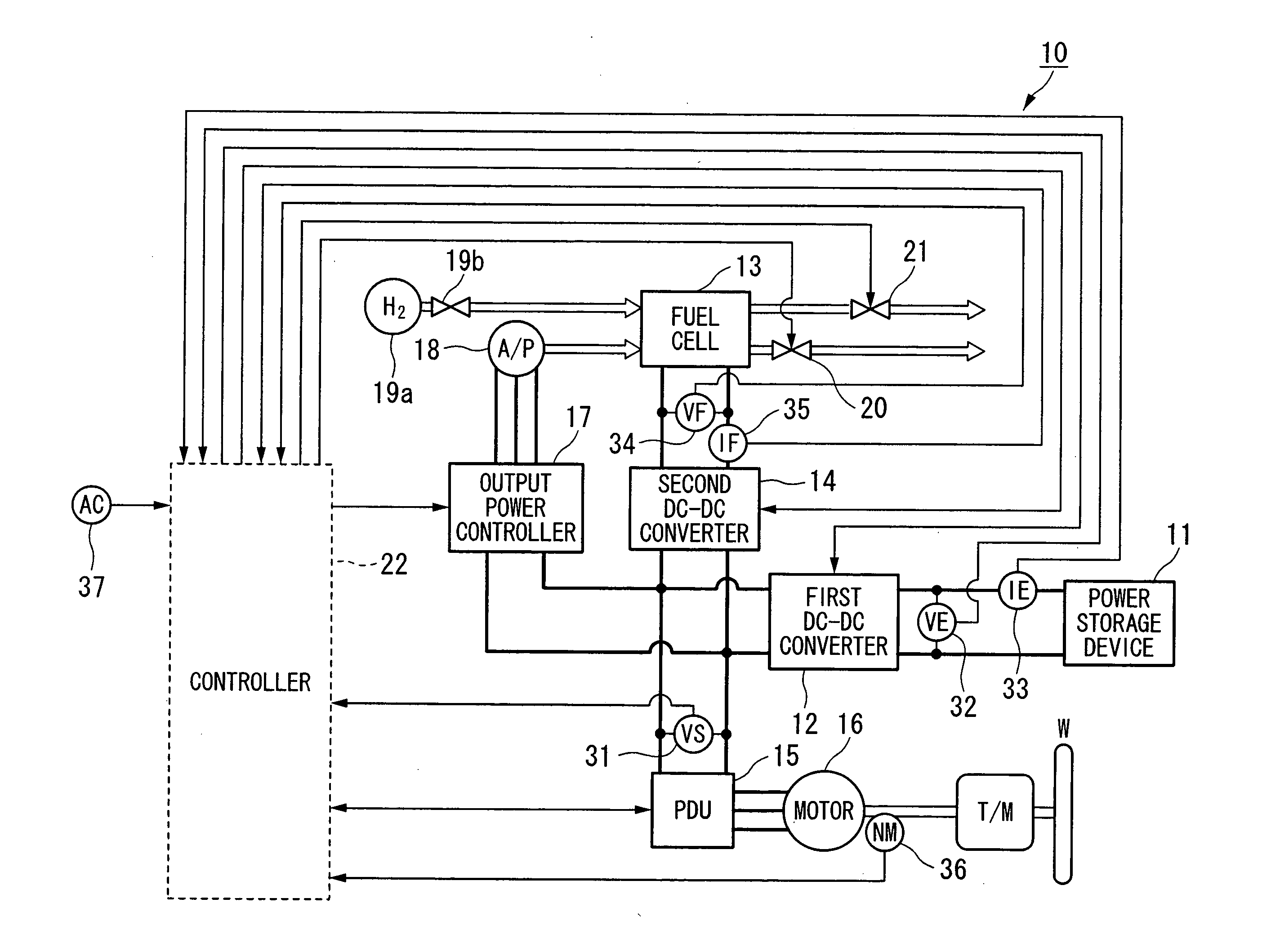
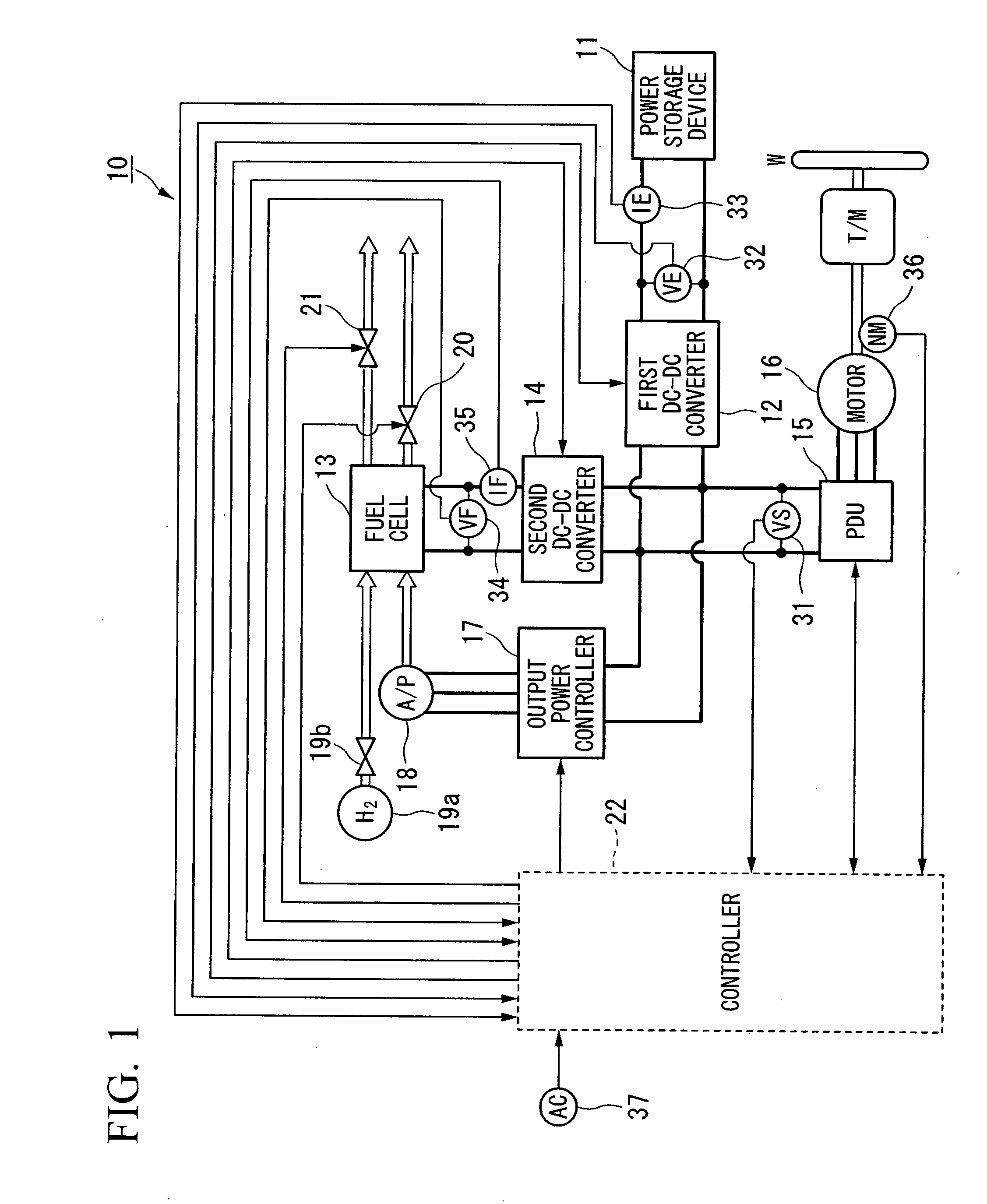
[0040] As shown in FIG. 1 for example, a fuel cell vehicle 10 of the present invention includes a power storage device 11, a first DC-DC converter 12, a fuel cell 13, a second DC-DC converter 14, a PDU (a Power Drive Unit) 15, a motor 16, an output power controller 17, an air-supply device (A / P) 18, a hydrogen tank 19a and a hydrogen supply valve 19b, a backpressure valve 20, a purging valve 21, a controller 22, a system voltage sensor 31, a first voltage sensor 32, a first current sensor 33, a second voltage sensor 34, a second current sensor 35, a motor rotation number sensor 36, and an accelerator-opening degree sensor 37.

[0041] The power storage device 11 is a capacitor or a battery or the like formed from, for example, an electric double layer condenser, an electrolytic condenser, or the like. The ...


PUM


Abstract

This control method for a fuel cell vehicle includes: a target motor output power obtaining step which obtains a target motor output power corresponding to an accelerator opening degree; and a high output power control step which controls operations of a first DC-DC converter and a second DC-DC converter, such that an output voltage of a power source becomes equal to or larger than a predetermined voltage that is required for securing a desired motor output power, when the target motor output power is larger than a predetermined output power threshold value.

Description

BACKGROUND OF THE INVENTION [0001] Priority is claimed on Japanese Patent Application No. 2006-026965, filed Feb. 3, 2006, the contents of which are incorporated herein by reference. FIELD OF THE INVENTION [0002] The present invention relates to a control method for a fuel cell vehicle, and a fuel cell vehicle. DESCRIPTION OF THE RELATED ART [0003] A conventional power controller is known which is provided with, for example: a charging controller which converts output voltage of a fuel cell to charging voltage of a secondary battery; and a discharging controller which converts discharging voltage of the secondary battery to output voltage of the fuel cell, wherein the output voltage of the fuel cell and the discharged voltage of the secondary battery which was converted so as to be substantially equivalent to the output voltage of the fuel cell, are input to a converter of a power converter (for example, refer to Japanese Unexamined Patent Application, First Publication No. 2003-208...

Claims


Application Information

Patent Timeline
IPC IPC(8): B60L8/00B60L9/00H01M2/02
CPCB60L11/1861Y02T90/34B60L2210/10B60L2250/26H01M8/04313H01M8/04559H01M8/04567H01M8/04589H01M8/04597H01M8/04753H01M8/04761H01M8/0488H01M8/04888H01M8/0491H01M8/04917H01M8/0494H01M8/04947H01M16/006Y02E60/50Y02T10/7044Y02T10/705Y02T10/7216B60L11/1887B60L58/12B60L58/40Y02E60/10Y02T10/70Y02T10/7072Y02T10/72Y02T90/40
Inventor AOYAGI, SATOSHISAEKI, HIBIKIKIMURA, KENICHIROTAKANOHASHI, HIROAKIABE, HIROYUKI
Owner HONDA MOTOR CO LTD
Why Eureka
Try Eureka