Vacuum Suction Head, And Vacuum Suction Device And Table Using The Same

a vacuum suction device and vacuum suction technology, applied in the direction of gripping heads, manipulators, load-engaging elements, etc., can solve the problems of suction failure and product defect of liquid crystal display panel substrate, and achieve the effect of enhancing the adhesion between the suction pad and the surface of the object to be sucked

Inactive Publication Date: 2007-08-30
MITSUBOSHI DIAMOND IND CO LTD
View PDF8 Cites 28 Cited by
  • Summary
  • Abstract
  • Description
  • Claims
  • Application Information

AI Technical Summary

Benefits of technology

[0031] According to the vacuum suction head of the present invention, since a shaft is elastically supported so as to be freely and slightly movable in an axial direction and in a direction diagonal to the axial direction (this mechanism is hereinafter referred to as freely following manner), the suction pad follows the surface of the object to be sucked, and reliably sucks the object to be sucked even if the object to be sucked has undulation. The adhesiveness between the suction pad and the surface of the object to be sucked can be enhanced irrespective of the shape of the object to be sucked. According to the vacuum suction device of the present invention, the plurality of vacuum suction heads can be arranged without performing an accurate height adjustment of the suction pad according to the size of the object to be sucked, and the suction force of each suction head is uniformly maintained. Further, the types of suction pad can be changed according to the surface condition, material, and flexural rigidity of the object to be sucked. A vacuum suction table having a plurality of suction heads arranged with a suction disk facing upwards, reliably floating the object to be sucked with compressed air, and sucking it after positioning can be realized.

Problems solved by technology

However, when a liquid crystal display panel substrate is sucked by the suction pad 51 of conventional example 1, a glass surface curves, uneven distribution occurs in a spacer interposed between the glass substrates, there has been a possible that product defect of the liquid crystal display panel substrate occurs as a result of uneven distribution, caused by curvature of glass surfaces, of spacers interposed between the glass substrates.
Thus, if central axis directions of the plurality of suction pads are all fixed in the same direction, the clearance between the suction pad and the liquid crystal display panel substrate may not be a predetermined value, or may form space thereby causing suction failure.

Method used


Image

  • Vacuum Suction Head, And Vacuum Suction Device And Table Using The Same
  • Vacuum Suction Head, And Vacuum Suction Device And Table Using The Same
  • Vacuum Suction Head, And Vacuum Suction Device And Table Using The Same

Examples


Embodiment Construction

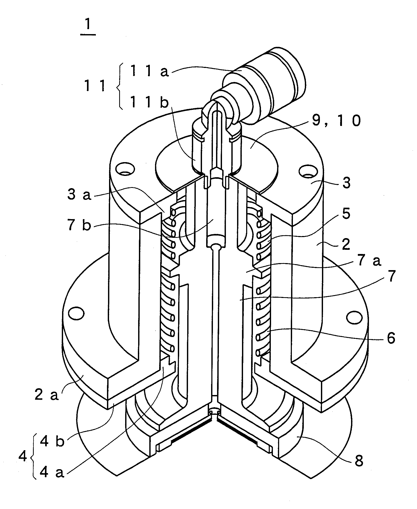
[0081] A vacuum suction head and vacuum suction device according to an embodiment of the present invention will now be described with reference to the drawings. FIG. 5 shows a fracture cross-section view showing an inner configuration of a vacuum suction head 1 in the present embodiment. FIG. 6 shows a cross-section view taken along a center axis of the vacuum suction head 1. FIG. 7 shows an exploded perspective view showing an attachment relationship of components of the vacuum suction head 1. The vacuum suction head 1 is configured including a casing part, a sucking part, and an elastic supporter. As shown in FIG. 6, a direction along the center axis of the vacuum suction head 1 is a z-axis direction, where an upward direction is “−” and a downward direction is +

[0082] The casing part includes a casing 2, a first casing plate 3 formed with a first opening, and a second casing plate 4 having second opening. A first spring 5 and a second spring 6 are arranged in the casing 2 as the ...


PUM


Abstract

A vacuum suction head of the present invention can be applied to a large-sized liquid crystal display panel and can reliably suck an object to be sucked even if the object has undulation or flexure. The suction head has a shaft, which holds a suction pad, and gas is charged into and discharged from the suction pad through a suction hole. A casing holds the shaft through first and second springs so as to be movable in the axial direction. Since the suction pad is elastically supported by the springs, the suction pad can reliably suck the object to be sucked having undulation or flexure. The vacuum suction head can be used for a vacuum suction device and a working table.

Description

TECHNICAL FIELD [0001] The present invention relates to a vacuum suction head used in sucking and conveying an object to be sucked such as a glass plate, liquid crystal display panel substrate, plate-shaped molded article made of resin, thin plate made of metal; and a vacuum suction device and a table for sucking the object to be sucked by one or a plurality of vacuum suction heads. BACKGROUND ART [0002] A liquid crystal display panel is a panel composed of two glass substrates, whose peripheral edges adhered using an adhesive (sealing agent) while maintaining a gap by particulate spacers between two glass substrates, and liquid crystal is injected into the gap. The liquid crystal display panel used in each display device differs greatly in a display size according to the application. In particular, a liquid crystal display panel for television receiver or monitor is becoming larger year after year, and accompanied therewith, a glass substrate used in the liquid crystal display pane...

Claims


Application Information

Patent Timeline
Patent Type & Authority Applications(United States)
IPC IPC(8): B25J15/06B25B11/00H01L21/683
CPCB25B11/005H01L21/6838B25J15/0616B25B11/007B25J15/06B25J19/00
Inventor NISHIO, YOSHITAKA
Owner MITSUBOSHI DIAMOND IND CO LTD
Why Eureka
Try Eureka