Microlens

a microlens and lens technology, applied in the field of microlens, can solve the problems of inability to form a hardcoat layer at a uniform thickness on a finely and complicated product such as microlens, and achieve the effects of preventing cracking of the inorganic compound layer itself, preventing cracking of the base lens material itself, and preventing wrinkling effectively

Inactive Publication Date: 2007-07-26
ORMON CORP
View PDF2 Cites 15 Cited by
  • Summary
  • Abstract
  • Description
  • Claims
  • Application Information

AI Technical Summary

Benefits of technology

[0021] According to the present invention, the adhesiveness between an inorganic compound layer and a base lens material under high-temperature high-humidity environment increases, without a hardcoat layer or an intermediate layer formed, and thus, it is possible to prevent separation of the inorganic compound layer from the base lens material in the shape of wrinkle and, as a result, to prevent wrinkling effectively.
[0022] It is also possible to prevent cracking of the inorganic compound layer itself under high-temperature high-humidity environment effectively.
[0023] It is further possible to prevent cracking of the base lens material itself by repeated temperature fluctuation effectively.

Problems solved by technology

Glass lenses have been used mainly, because they were very superior in optical properties, but were disadvantageous in processability when used in applications that demand processing into various shapes.
However, presence of an inorganic compound layer such as antireflective layer formed directly on the surface of resin lens caused a problem that there were cracking and wrinkling of the inorganic compound layer generated under high-temperature high-humidity environment because of insufficient adhesiveness between the resin lens and the inorganic compound layer.
A hardcoat layer is generally formed between a resin lens and an inorganic compound for improvement in adhesiveness between them, but it is technically difficult to form a hardcoat layer at a uniform thickness on a finely and complicated shaped product such as microlens.
However, the method had a disadvantage of demanding additional special step.
The method is aimed at preventing cracking and wrinkling caused during deposition of the inorganic compound layer and caused by repeated temperature fluctuation, and does not solve the problem of cracking and wrinkling of the inorganic compound under high-temperature high-humidity environment.
However, the method is aimed at improving thermal stability of resin-lens refractive index, and not at improving high-temperature high-humidity resistance of the inorganic compound layer such as antireflective layer formed on microlens.
The oxide fine particles are added for preservation of the shape formed by the stamper before photo-hardening, and thus, the method is not aimed at improving high-temperature high-humidity resistance of the inorganic compound layer formed on hardened product surface.

Method used


Image

  • Microlens
  • Microlens

Examples


examples

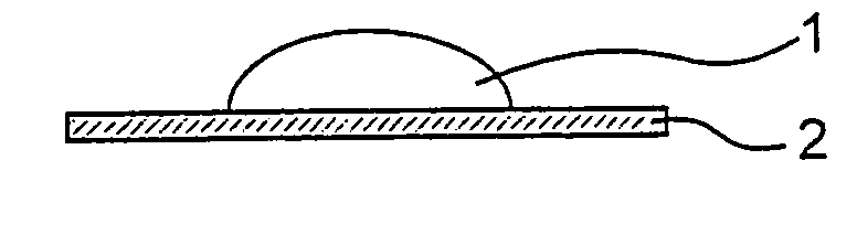
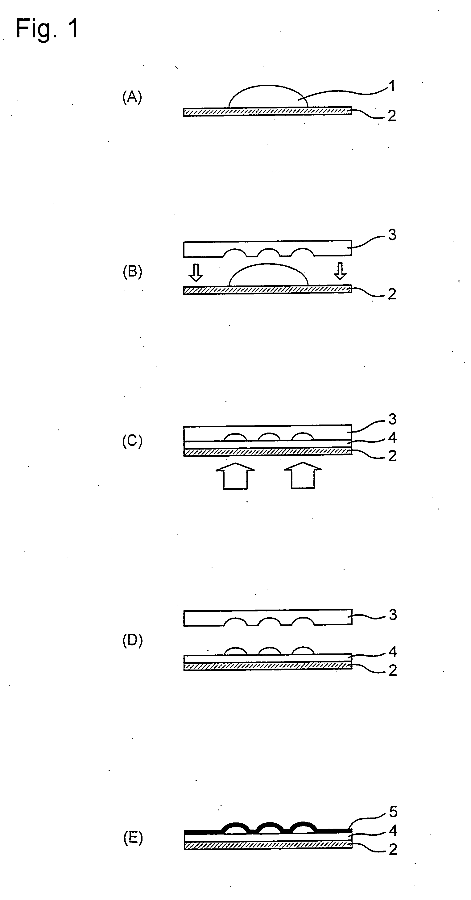
[0077] (Preparation of Microlens)

[0078] Polymerizable monomers and silica sol were mixed in the amounts (by weight) shown in each of Tables 1 to 4, and the solvent derived from silica sol was removed under reduced pressure, to give each polymerizable composition. When a silane-coupling agent (MPS or ESC) was added, the silica sol and the silane-coupling agent were mixed at the weight ratio of silica to the silane-coupling agent shown in each Table, and the mixture was stirred for 24 hours, before the polymerizable monomer and the silica sol were mixed. The weight rate of silica in each Table is a weight ratio of the silica sol solid matter.

[0079] Then, a base microlens material was molded by using each of the polymerizable compositions by a stamper method. Specifically, a polymerization initiator was added to the polymerizable composition to a predetermined amount, and the polymerizable composition was applied on a glass plate in an amount of several grams and pressed with a stamp...


PUM

PropertyMeasurementUnit
diameteraaaaaaaaaa
particle diameteraaaaaaaaaa

Abstract

Provided is a microlens having an inorganic compound layer directly formed on the surface of a base lens material that is resistant to cracking and wrinkling of the inorganic compound layer under high-temperature and high-humidity environment and also to cracking of the base lens material by repeated temperature fluctuation, and an optical device using the microlens. A microlens, comprising a hardened product obtained by polymerization of a polymerizable composition containing a polymerizable monomer and metal oxide fine particles having an average diameter of 1 to 80 nm as essential components and an inorganic compound layer coated on the surface thereof. An optical device equipped with the microlens.

Description

TECHNICAL FIELD [0001] The present invention relates to a microlens, specifically a microlens of a hardened product prepared by polymerization of a polymerizable composition, having an inorganic compound layer coated on the surface thereof. BACKGROUND ART [0002] In the recent rapid movement for reduction in size, thickness and weight and for improvement in performance such as high definition of optical devices, there exists a need for miniaturization and improvement in performance also in optical parts used in optical devices. There are more requirements, for example, for improvement in resistance to use environment and improvement in performance, especially in lens-based optical parts used in optical devices. Glass lenses have been used mainly, because they were very superior in optical properties, but were disadvantageous in processability when used in applications that demand processing into various shapes. Accordingly, lenses of a UV-hardening or thermosetting resin composition ...

Claims


Application Information

Patent Timeline
Patent Type & Authority Applications(United States)
IPC IPC(8): G03C5/00C08F20/28G02B1/04G02B3/00
CPCG02B3/0031G02B3/00
Inventor OZAWA, NAOSHIFUNAKI, KENJIKITAMURA, KYOJINAKAMURA, MASAKIWATANABE, YUJIFUKUHARA, TOMOHIROMATSUMOTO, RYOICHI
Owner ORMON CORP
Why Eureka
Try Eureka