Method And Arrangement For Determining The Spatial Frequency Of A Signal

a spatial frequency and signal technology, applied in the direction of wind-induced force reduction, linear waveguide fed arrays, instruments, etc., can solve the problem of increasing hardware costs

Active Publication Date: 2007-08-30
TELEFON AB LM ERICSSON (PUBL)
View PDF2 Cites 11 Cited by
  • Summary
  • Abstract
  • Description
  • Claims
  • Application Information

AI Technical Summary

Benefits of technology

[0006] An object of the present invention is to provide a method and arrangement for unambiguously determining the direction to an emi

Problems solved by technology

However, combining signals from individual element antennas tend to introduce some problems: The element antennas will easily interfere with each other and create an overall antenna diagram with so called grating

Method used


Image

  • Method And Arrangement For Determining The Spatial Frequency Of A Signal
  • Method And Arrangement For Determining The Spatial Frequency Of A Signal
  • Method And Arrangement For Determining The Spatial Frequency Of A Signal

Examples


Embodiment Construction

[0016] The invention will be described in reference to a composite layered antenna panel as disclosed in International Patent Application PCT / NO2004 / 000407 with title “An antenna arrangement” filed by the present applicant, even though the invention may be applied to any type of antenna array.

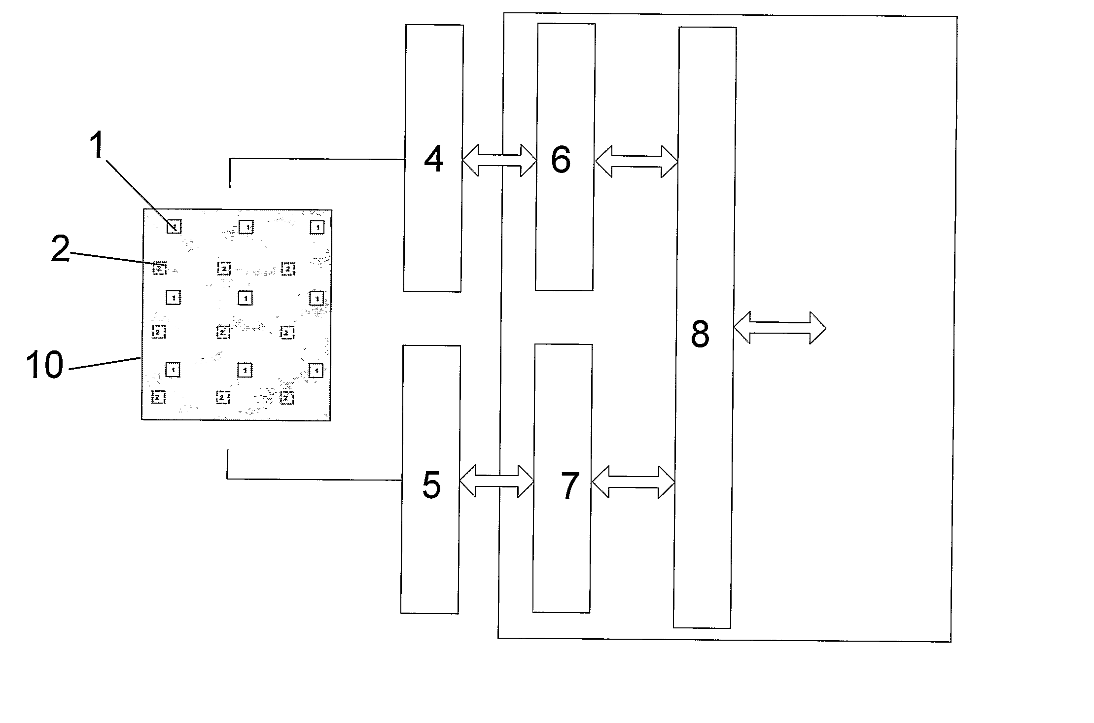
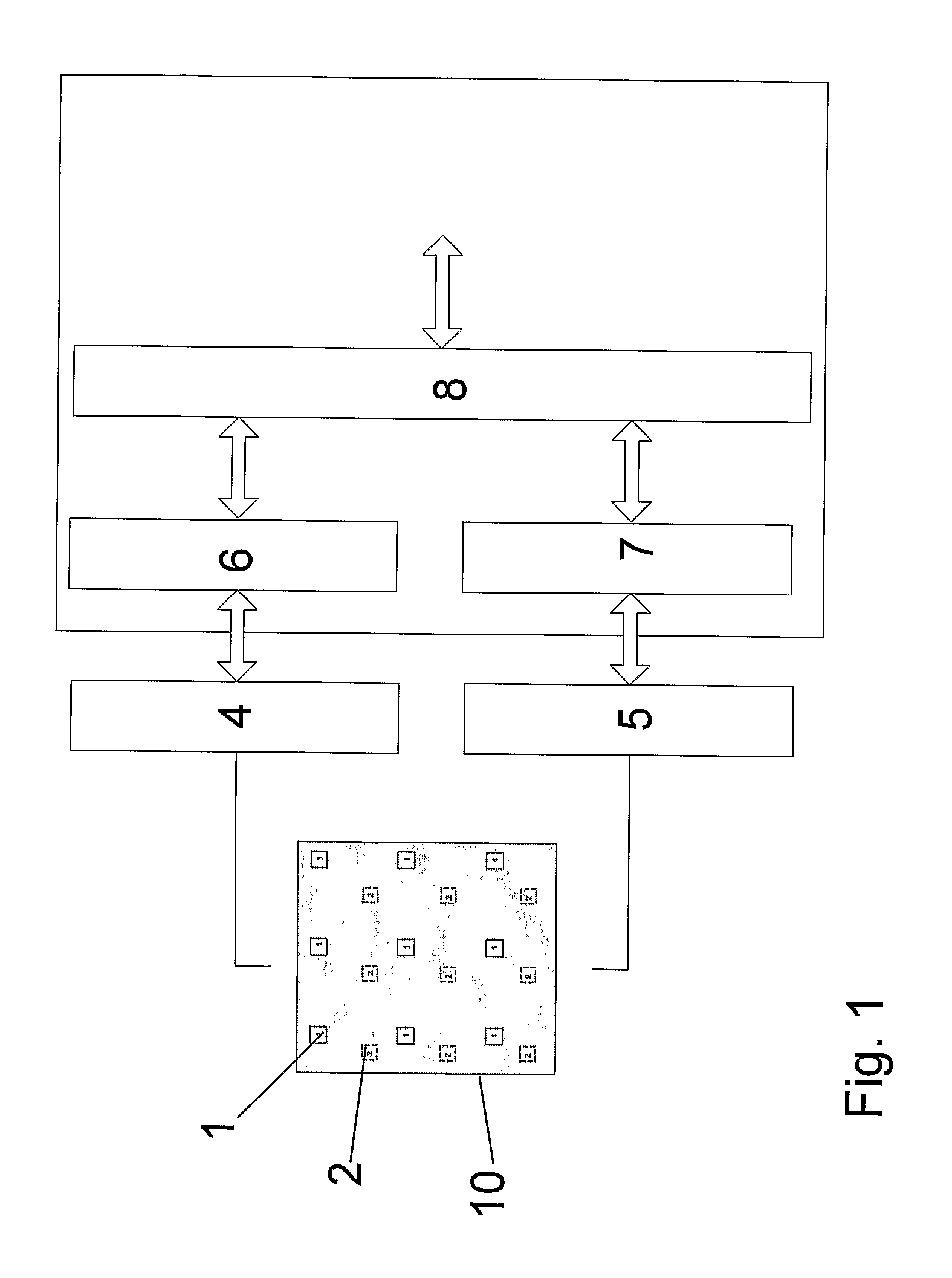
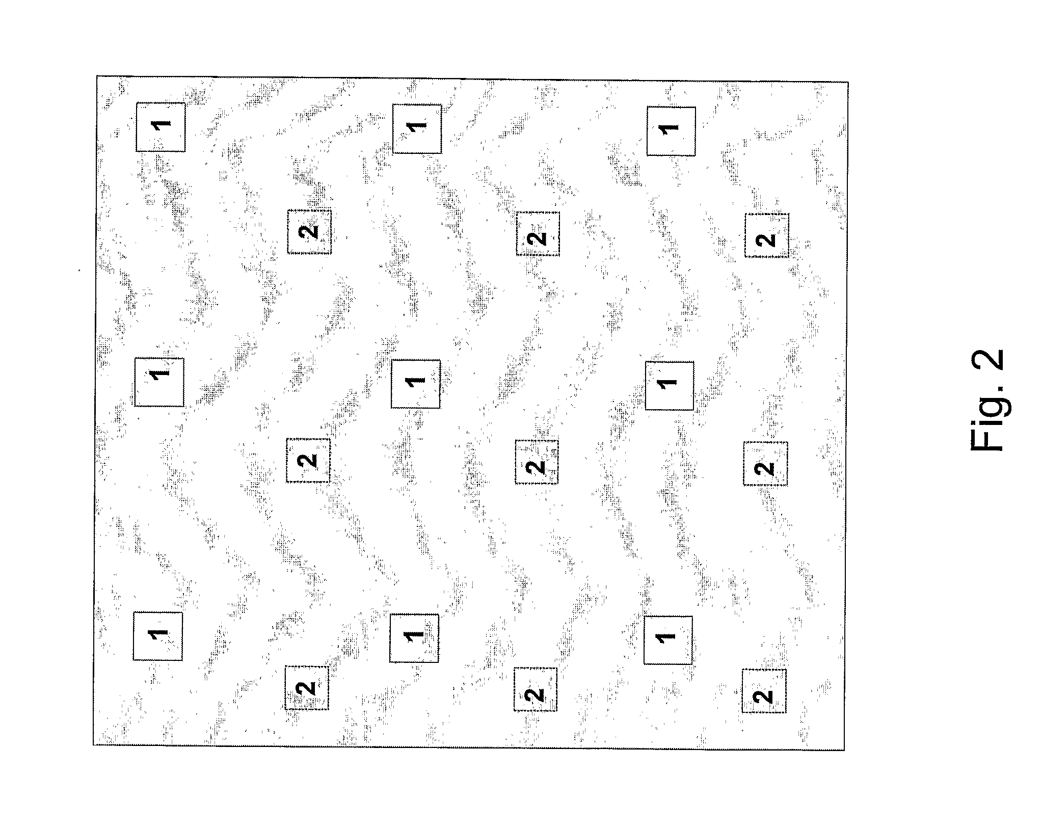
[0017]FIG. 1 shows a direction finder system including an antenna panel 10. The antenna panel includes two set of patches 1, 2 organized in separate matrices. The signals picked up by each patch set are processed in separate receiver chains 4, 5. The receiver chains output digitized signals. Preferably, each receiver chain comprises separate receivers for each individual patch if economy and space permits. The digitized signals are combined in beamforming circuitry 6, 7. The signals from the patch sets 1, 2 are compared in signal processing circuitry 8 in order to determine the direction of arrival for a signal received by the antenna panel 10. The beamforming properties of the antenna is amon...


PUM


Abstract

A method and arrangement for finding the direction to an emitter source by determining the spatial frequency of a signal received from the source in a sensor panel and comparing the spatial frequency with the instantaneous frequency. The panel includes a first matrix of sensors and a second matrix of sensors interleaved with the first matrix. The spatial frequency is determined by comparing the signals received by the first and second sensor matrices.

Description

FIELD OF THE INVENTION [0001] The present invention relates to stacking of sensors and beam steering of sensor arrays in general, but find particular application in direction-finding systems and ESM systems. TECHNICAL BACKGROUND [0002] Radio frequency emitters (radars, satellite uplink stations, cell-phone base stations, relay links) can be detected, analysed, and geo-referenced from a remote observation platform. This is achieved using a sensor with an antenna system for detecting the radiation, connected to a receiver and processing system. These systems can be deployed from satellites, aircraft, UAVs, ships vehicles or mounted in masts. [0003] Typical solutions employ radio receiver systems operating in the frequency bands 1 through 12 GHz. These systems employ multiple receiving antennas and multiple receivers to derive a course direction to the emitters. [0004] In one method, the direction to the emitters is determined by comparing the phases of signals received in two or more ...

Claims


Application Information

Patent Timeline
IPC IPC(8): G01S5/02G01S3/02G01S3/04G01S3/48G01S5/00G01S5/04G01S7/00G01S7/02H01Q1/00H01Q1/02H01Q1/28H01Q9/04H01Q15/14H01Q21/00H03M1/12H04B1/28
CPCG01S3/023H04B1/28G01S3/48G01S5/0009G01S5/04G01S7/003G01S7/021H01Q1/005H01Q1/02H01Q1/288H01Q9/0457H01Q15/147H01Q21/005H01Q21/0087G01S3/043
Inventor HJELMSTAD, JENS FREDRIK
Owner TELEFON AB LM ERICSSON (PUBL)
Why Eureka
Try Eureka