Condenser microphone

a condenser microphone and microphone technology, applied in the direction of diaphragm construction, loudspeaker, electrostatic transducer, etc., can solve the problems of film separation, reduced sensitivity of the condenser microphone, and relatively large residual stresses in the diaphragm, so as to reduce the tensile stress of the diaphragm and high sensitivity

Inactive Publication Date: 2007-08-30
YAMAHA CORP
View PDF4 Cites 135 Cited by
  • Summary
  • Abstract
  • Description
  • Claims
  • Application Information

AI Technical Summary

Benefits of technology

[0010] It is an object of the present invention to provide a condenser microph

Problems solved by technology

Hence, there is still a problem in that relatively large residual stresses remain in the diaphragms.
This may cause a reduction of the sensitivity of the condenser microphone.
When the thickness of the film lying between the diaphragm and plate is increased, cracks and film separation may likely occur.
However, combining two wafers results in complicated manufacturing process and thus increases the manufacturing cost.
In addition, the condenser microphone disclosed in the aforementioned paper suffers from high tensile stress remaining in the diaphragm.
This reduces the amplitude of vibration of the diaphragm due to sound pressure applied thereto and thus reduces the sensitivity of the condenser microphone.
That is, it is very difficu

Method used


Image

  • Condenser microphone
  • Condenser microphone
  • Condenser microphone

Examples


first embodiment

1. First Embodiment

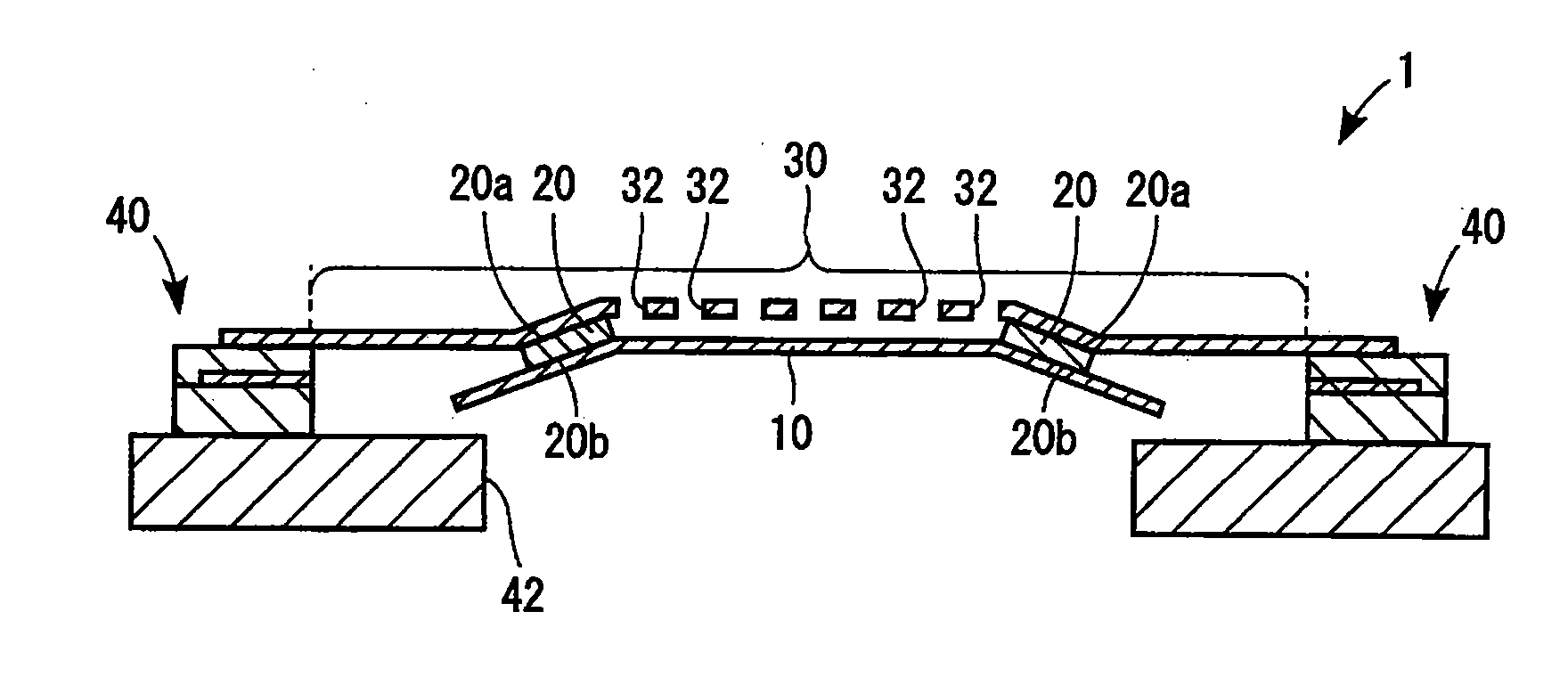
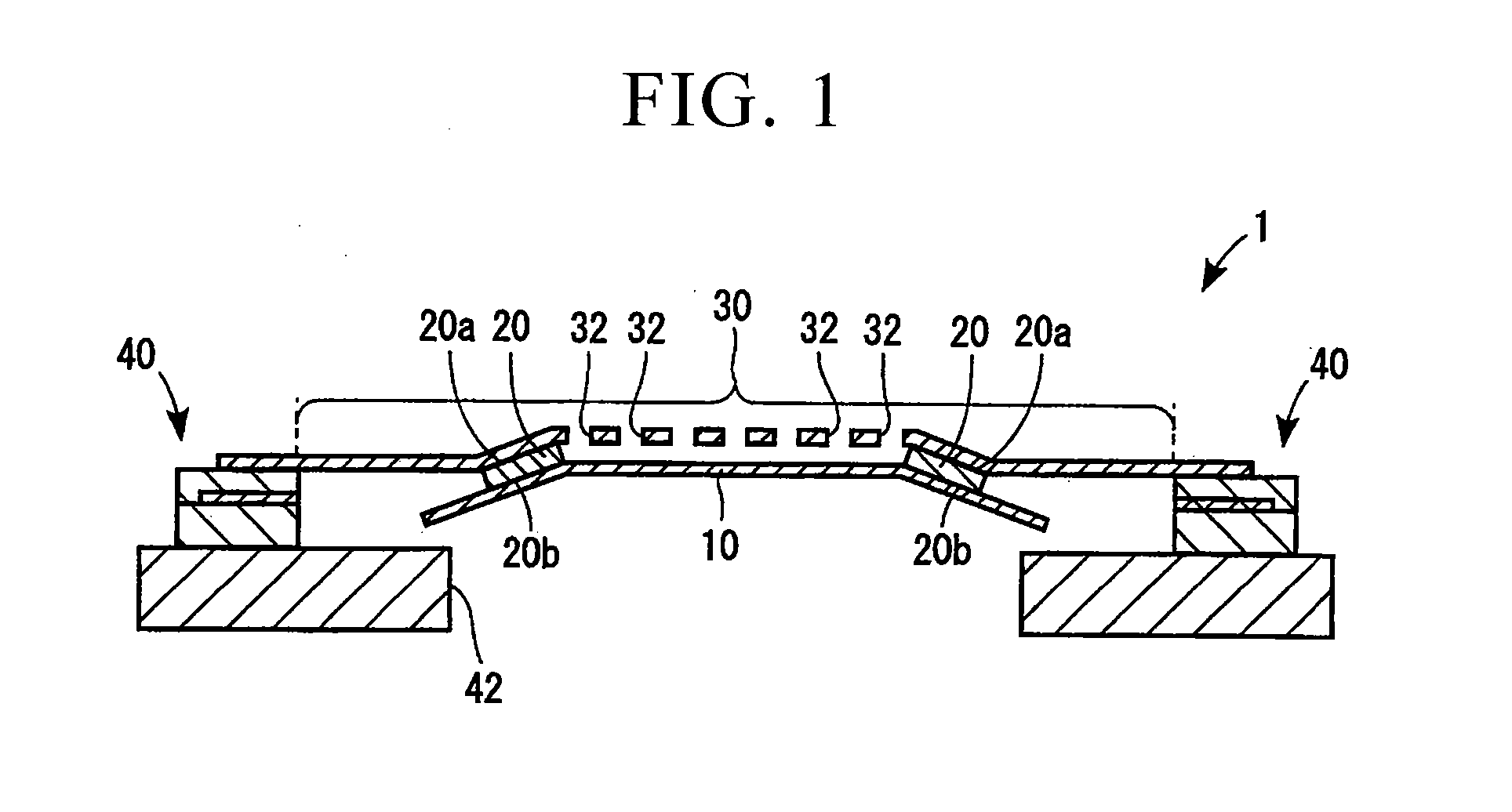
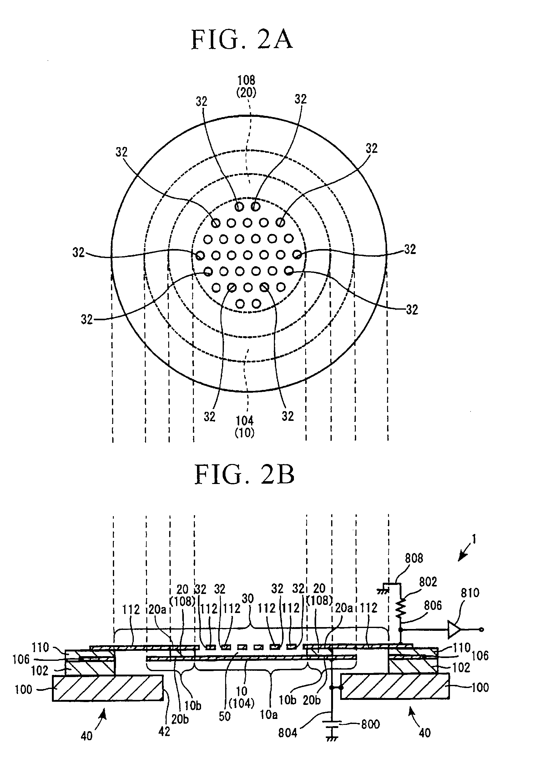
[0203]FIGS. 2A, 2B, and 2C show the overall constitution of a condenser microphone 1 just after the manufacturing thereof in accordance with a first embodiment of the present invention. The condenser microphone 1 is a silicon capacitor microphone, which is produced by way of a semiconductor manufacturing process. The condenser microphone 1 has a sensing portion (see a cross-sectional view of FIG. 2B) and a detecting portion (see the circuitry shown in FIG. 2B).

[0204] (a) Constitution of Sensing Portion

[0205] The sensing portion of the condenser microphone 1 is constituted of a diaphragm 10, a spacer 20, a back plate 30, and supports 40.

[0206] The diaphragm 10 is composed of a conductive film 104, which is a semiconductor film composed of polycrystal silicon (or polysilicon), for example. The diaphragm 10 having a conductivity functions as a moving electrode, wherein the diaphragm 10 can be constituted of a plurality of films including an insulating film and a c...

second embodiment

2. Second Embodiment

[0270]FIGS. 18A and 18B show a condenser microphone in accordance with a second embodiment of the present invention. FIG. 18A is a plan view showing a back plate and its associated parts. A condenser microphone 1001 is a silicon capacitor microphone, which is manufactured using the semiconductor manufacturing process. The condenser microphone 1001 includes a sensing portion (see mechanical parts shown in FIG. 18B) and a detecting portion (see the circuitry shown in FIG. 18B).

[0271] (a) Constitution of Sensing Portion

[0272] As shown in FIGS. 18A and 18B, the sensing portion of the condenser microphone 1001 is constituted of a diaphragm 1010, a spacer 1020, a back plate 1030, bridges 1040, and supports 1050.

[0273] The diaphragm 1010 is formed using a conductive film 1104, which functions as a moving electrode as well. Specifically, the diaphragm 1010 is a semiconductor film composed of polycrystal silicon (or polysilicon), in which the thickness thereof ranges f...

third embodiment

3. Third Embodiment

[0335] A condenser microphone 2001 according to a third embodiment of the present invention will be described with reference to FIGS. 30A to 30C and FIG. 31, wherein FIG. 30A is a cross-sectional view taken along line A1-A1 in FIG. 31; FIG. 30B is a cross-sectional view taken along line B1-B1 in FIG. 31; and FIG. 30C is a horizontal sectional view taken along line C1-C1 in FIG. 30A.

[0336] The condenser microphone 2001 is a silicon capacitor microphone, which is manufactured by way of the semiconductor manufacturing process. The condenser microphone 2001 has a sensing portion (whose mechanical parts are shown in FIGS. 30A and 30B) and a detecting portion (see the circuitry shown in FIG. 30A).

[0337] (a) Constitution of Sensing Portion

[0338] The sensing portion of the condenser microphone 2001 is constituted of a diaphragm 2010, a back plate 2030, and supports 2040. The diaphragm 2010 is formed using the prescribed portion of a conductive film 2114 that is not fix...


PUM


Abstract

A condenser microphone includes a support, a plate having a fixed electrode bridged across the supports, a diaphragm, which has a moving electrode at a center portion thereof and which vibrates due to sound waves applied thereto, and a spacer, in which a first end is fixed to the plate, and a second end is fixed to the near-end portion of the diaphragm so as to surround the center portion of the diaphragm, wherein an air gap is formed between the plate and the diaphragm. This reduces the tensile stress of the diaphragm so as to increase the amplitude of vibration of the diaphragm. Hence, it is possible to increase the sensitivity of the condenser microphone. A structure constituted of the plate, the diaphragm, and the spacer is bridged across the support by means of the bridges, which absorb the residual stress of the diaphragm due to the deformation thereof.

Description

TECHNICAL FIELD [0001] The present invention relates to condenser microphones (or capacitor microphones) having diaphragms and plates, which are manufactured using semiconductor films and which are adapted to MEMS (Micro Electro Mechanical System). [0002] This application claims priority on Japanese Patent Application No. 2006-48252 (filed Feb. 24, 2006), Japanese Patent Application No. 2006-65402 (filed Mar. 10, 2006), Japanese Patent Application No. 2006-65263 (filed Mar. 10, 2006), Japanese Patent Application No. 2006-97305 (filed Mar. 31, 2006), and Japanese Patent Application No. 2006-89679 (filed Mar. 29, 2006), the contents of which are incorporated herein by reference. BACKGROUND ART [0003] Conventionally, various types of condenser microphones (or capacitor microphones), which can be manufactured in accordance with manufacturing processes of semiconductor devices, are known, wherein they are constituted using plates and diaphragms both having electrodes such that plates and...

Claims


Application Information

Patent Timeline
IPC IPC(8): H04R25/00
CPCB81B3/0072B81B2201/0257H04R31/006H04R7/06H04R19/005B81B2203/0109H04R19/016H04R2201/003
Inventor SUZUKI, YUKITOSHISUZUKI, TOSHIHISA
Owner YAMAHA CORP
Why Eureka
Try Eureka